JAJSDS2A September   2017  – February 2022 TIC10024-Q1

PRODUCTION DATA  

  1. 特長
  2. アプリケーション
  3. 概要
  4. Revision History
  5. Pin Configuration and Functions
  6. Specifications
    1. 6.1 Absolute Maximum Ratings
    2. 6.2 ESD Ratings
    3. 6.3 Recommended Operating Conditions
    4. 6.4 Thermal Information
    5. 6.5 Electrical Characteristics
    6. 6.6 Timing Requirements
    7. 6.7 Typical Characteristics
  7. Parameter Measurement Information
  8. Detailed Description
    1. 8.1 Overview
    2. 8.2 Functional Block Diagram
    3. 8.3 Feature Description
      1. 8.3.1  VS Pin
      2. 8.3.2  VDD Pin
      3. 8.3.3  Device Initialization
      4. 8.3.4  Device Trigger
      5. 8.3.5  Device Reset
        1. 8.3.5.1 VS Supply POR
        2. 8.3.5.2 Hardware Reset
        3. 8.3.5.3 Software Reset
      6. 8.3.6  VS Under-Voltage (UV) Condition
      7. 8.3.7  VS Over-Voltage (OV) Condition
      8. 8.3.8  Switch Inputs Settings
        1. 8.3.8.1 Input Current Source and Sink Selection
        2. 8.3.8.2 Input Enable Selection
        3. 8.3.8.3 Thresholds Adjustment
        4. 8.3.8.4 Wetting Current Configuration
      9. 8.3.9  Interrupt Generation and INT Assertion
        1. 8.3.9.1 INT Pin Assertion Scheme
        2. 8.3.9.2 Interrupt Idle Time (tINT_IDLE) Time
        3. 8.3.9.3 Microcontroller Wake-Up
        4. 8.3.9.4 Interrupt Enable / Disable And Interrupt Generation Conditions
        5. 8.3.9.5 Detection Filter
      10. 8.3.10 Temperature Monitor
        1. 8.3.10.1 Temperature Warning (TW)
        2. 8.3.10.2 Temperature Shutdown (TSD)
      11. 8.3.11 Parity Check And Parity Generation
      12. 8.3.12 Cyclic Redundancy Check (CRC)
    4. 8.4 Device Functional Modes
      1. 8.4.1 Continuous Mode
      2. 8.4.2 Polling Mode
      3. 8.4.3 Additional Features
        1. 8.4.3.1 Clean Current Polling (CCP)
        2. 8.4.3.2 Wetting Current Auto-Scaling
  9. Programming
    1. 9.1 SPI Communication Interface Buses
      1. 9.1.1 Chip Select ( CS)
      2. 9.1.2 System Clock (SCLK)
      3. 9.1.3 Slave In (SI)
      4. 9.1.4 Slave Out (SO)
    2. 9.2 SPI Sequence
      1. 9.2.1 Read Operation
      2. 9.2.2 Write Operation
      3. 9.2.3 Status Flag
    3. 9.3 Programming Guidelines
    4. 9.4 Register Maps
  10. 10Application and Implementation
    1. 10.1 Application Information
    2. 10.2 Digital Switch Detection in Automotive Body Control Module
      1. 10.2.1 Design Requirements
      2. 10.2.2 Detailed Design Procedure
      3. 10.2.3 Application Curves
    3. 10.3 Systems Examples
      1. 10.3.1 Using TIC10024-Q1 in a 12 V Automotive System
  11. 11Power Supply Recommendations
  12. 12Layout
    1. 12.1 Layout Guidelines
    2. 12.2 Layout Example
  13. 13Device and Documentation Support
    1. 13.1 Receiving Notification of Documentation Updates
    2. 13.2 Community Resources
    3. 13.3 Trademarks
  14. 14Mechanical, Packaging, and Orderable Information

パッケージ・オプション

メカニカル・データ(パッケージ|ピン)
サーマルパッド・メカニカル・データ
発注情報

概要

TIC10024-Q1 は、12V 車載システムで外付けスイッチの状態を検出するように設計された、先進的なマルチ・スイッチ検出インターフェイス (MSDI) です。TIC10024-Q1 は、可変スレッショルドを備えたコンパレータにより、MCU から独立してデジタル・スイッチを監視します。このデバイスは、最大 24 の直接スイッチ入力を監視し、そのうち 10 の入力はグランドまたはバッテリに接続されているスイッチを監視するよう構成できます。各種のアプリケーション・シナリオに対応するため、各入力に 6 つの固有のウェット電流設定をプログラムできます。このデバイスは、すべてのスイッチ入力でウェークアップ動作をサポートするため、MCU を継続的にアクティブにしておく必要がなくなり、システムの消費電力を削減できます。また TIC10024-Q1 には、フォルト検出機能と ESD 保護機能が統合されているため、システムの安定性も向上します。TIC10024-Q1 は、連続モードとポーリング・モードという 2 つの動作モードをサポートしています。連続モードでは、ウェット電流が連続的に供給されます。ポーリング・モードでは、プログラマブル・タイマに基づいてウェット電流が定期的にオンになり、入力状態をサンプリングするため、システムの消費電力を大幅に削減できます。

製品情報
部品番号パッケージ(1)本体サイズ (公称)
TIC10024-Q1TSSOP (38)9.70mm × 4.40mm
利用可能なパッケージについては、このデータシートの末尾にある注文情報を参照してください。
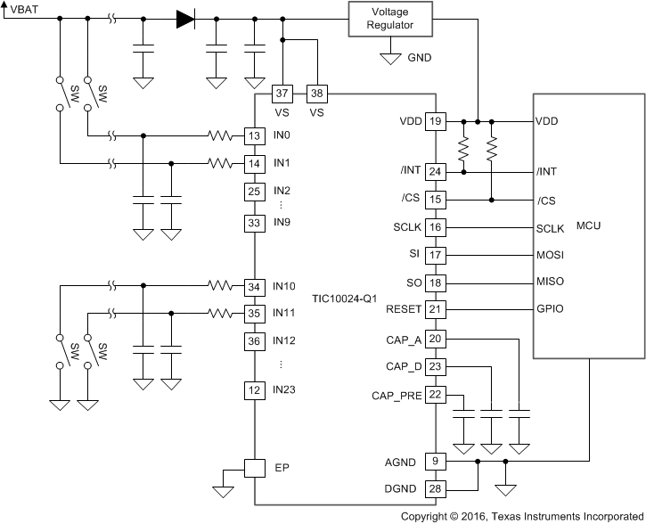
GUID-80B5F99F-7D01-4BD3-B5AA-C8AF0EBFFAC6-low.gif概略回路図