-
TIC12400 24入力マルチ・スイッチ検出インターフェイス(MSDI)ADC内蔵、可変ウェット電流対応
- 1 特長
- 2 アプリケーション
- 3 概要
- 4 改訂履歴
- 5 Pin Configuration and Functions
- 6 Specifications
- 7 Parameter Measurement Information
-
8 Detailed Description
- 8.1 Overview
- 8.2 Functional Block Diagram
- 8.3
Feature Description
- 8.3.1 VS Pin
- 8.3.2 VDD Pin
- 8.3.3 Device Initialization
- 8.3.4 Device Trigger
- 8.3.5 Device Reset
- 8.3.6 VS Under-Voltage (UV) Condition
- 8.3.7 VS Over-Voltage (OV) Condition
- 8.3.8 Switch inputs Settings
- 8.3.9 Interrupt Generation and INT Assertion
- 8.3.10 Temperature Monitor
- 8.3.11 Parity Check And Parity Generation
- 8.3.12 Cyclic Redundancy Check (CRC)
- 8.4 Device Functional Modes
- 8.5 Programming
- 8.6
Register Maps
- 8.6.1 DEVICE_ID register (Offset = 1h) [reset = 20h]
- 8.6.2 INT_STAT Register (Offset = 2h) [reset = 1h]
- 8.6.3 CRC Register (Offset = 3h) [reset = FFFFh]
- 8.6.4 IN_STAT_MISC Register (Offset = 4h) [reset = 0h]
- 8.6.5 IN_STAT_COMP Register (Offset = 5h) [reset = 0h]
- 8.6.6 IN_STAT_ADC0 Register (Offset = 6h) [reset = 0h]
- 8.6.7 IN_STAT_ADC1 Register (Offset = 7h) [reset = 0h]
- 8.6.8 IN_STAT_MATRIX0 Register (Offset = 8h) [reset = 0h]
- 8.6.9 IN_STAT_MATRIX1 Register (Offset = 9h) [reset = 0h]
- 8.6.10 ANA_STAT0 Register (Offset = Ah) [reset = 0h]
- 8.6.11 ANA_STAT1 Register (Offset = Bh) [reset = 0h]
- 8.6.12 ANA_STAT2 Register (Offset = Ch) [reset = 0h]
- 8.6.13 ANA_STAT3 Register (Offset = Dh) [reset = 0h]
- 8.6.14 ANA_STAT4 Register (Offset = Eh) [reset = 0h]
- 8.6.15 ANA_STAT5 Register (Offset = Fh) [reset = 0h]
- 8.6.16 ANA_STAT6 Register (Offset = 10h) [reset = 0h]
- 8.6.17 ANA_STAT7 Register (Offset = 11h) [reset = 0h]
- 8.6.18 ANA_STAT8 Register (Offset = 12h) [reset = 0h]
- 8.6.19 ANA_STAT9 Register (Offset = 13h) [reset = 0h]
- 8.6.20 ANA_STAT10 Register (Offset = 14h) [reset = 0h]
- 8.6.21 ANA_STAT11 Register (Offset = 15h) [reset = 0h]
- 8.6.22 ANA_STAT12 Register (Offset = 16h) [reset = 0h]
- 8.6.23 CONFIG Register (Offset = 1Ah) [reset = 0h]
- 8.6.24 IN_EN Register (Offset = 1Bh) [reset = 0h]
- 8.6.25 CS_SELECT Register (Offset = 1Ch) [reset = 0h]
- 8.6.26 WC_CFG0 Register (Offset = 1Dh) [reset = 0h]
- 8.6.27 WC_CFG1 Register (Offset = 1Eh) [reset = 0h]
- 8.6.28 CCP_CFG0 Register (Offset = 1Fh) [reset = 0h]
- 8.6.29 CCP_CFG1 Register (Offset = 20h) [reset = 0h]
- 8.6.30 THRES_COMP Register (Offset = 21h) [reset = 0h]
- 8.6.31 INT_EN_COMP1 Register (Offset = 22h) [reset = 0h]
- 8.6.32 INT_EN_COMP2 Register (Offset = 23h) [reset = 0h]
- 8.6.33 INT_EN_CFG0 Register (Offset = 24h) [reset = 0h]
- 8.6.34 INT_EN_CFG1 Register (Offset = 25h) [reset = 0h]
- 8.6.35 INT_EN_CFG2 Register (Offset = 26h) [reset = 0h]
- 8.6.36 INT_EN_CFG3 Register (Offset = 27h) [reset = 0h]
- 8.6.37 INT_EN_CFG4 Register (Offset = 28h) [reset = 0h]
- 8.6.38 THRES_CFG0 Register (Offset = 29h) [reset = 0h]
- 8.6.39 THRES_CFG1 Register (Offset = 2Ah) [reset = 0h]
- 8.6.40 THRES_CFG2 Register (Offset = 2Bh) [reset = 0h]
- 8.6.41 THRES_CFG3 Register (Offset = 2Ch) [reset = X]
- 8.6.42 THRES_CFG4 Register (Offset = 2Dh) [reset = X]
- 8.6.43 THRESMAP_CFG0 Register (Offset = 2Eh) [reset = 0h]
- 8.6.44 THRESMAP_CFG1 Register (Offset = 2Fh) [reset = 0h]
- 8.6.45 THRESMAP_CFG2 Register (Offset = 30h) [reset = 0h]
- 8.6.46 Matrix Register (Offset = 31h) [reset = 0h]
- 8.6.47 Mode Register (Offset = 32h) [reset = 0h]
- 8.7 Programming Guidelines
- 9 Application and Implementation
- 10Power Supply Recommendations
- 11Layout
- 12デバイスおよびドキュメントのサポート
- 13メカニカル、パッケージ、および注文情報
- 重要なお知らせ
パッケージ・オプション
メカニカル・データ(パッケージ|ピン)
- DCP|38
サーマルパッド・メカニカル・データ
- DCP|38
発注情報
DATA SHEET
TIC12400 24入力マルチ・スイッチ検出インターフェイス(MSDI)ADC内蔵、可変ウェット電流対応
このリソースの元の言語は英語です。 翻訳は概要を便宜的に提供するもので、自動化ツール (機械翻訳) を使用していることがあり、TI では翻訳の正確性および妥当性につきましては一切保証いたしません。 実際の設計などの前には、ti.com で必ず最新の英語版をご参照くださいますようお願いいたします。
1 特長
- 6.5V~35Vの電源電圧(VS)で動作し、過電圧および低電圧警告機能を搭載
- 最大24の直接スイッチ入力を監視し、そのうち10の入力はグランドまたは電源に接続されているスイッチを監視するよう構成可能
- スイッチ入力は40Vと、-24Vまでの逆電源に耐えられる
- 6つの構成可能なウェット電流設定:
(0mA、1mA、2mA、5mA、10mA、15mA) - 内蔵の10ビットADCによるマルチポジション・アナログ・スイッチ監視
- 内蔵コンパレータに、入力を監視するため4つのスレッショルドをプログラム可能
- ポーリング・モードでの極めて低い動作電流:
標準値68μA (tPOLL=64ms、tPOLL_ACT=128μs、
24の入力がすべてアクティブ、コンパレータ・モード、すべてのスイッチが開) - 3.3V/5Vのシリアル・ペリフェラル・インターフェイス(SPI)プロトコルを使用してMCUに直接接続
- 割り込み生成により、すべての入力でウェークアップ動作をサポート
- 電源および温度センシングを内蔵
- 適切な外付けコンポーネントにより、IEC 61000-4-2に準拠した入力ピンで、±8kVの接触放電ESD保護を実現
- 38ピンTSSOPパッケージ
2 アプリケーション
- 信号測定
- PLC、DCS、およびPAC
- 計装機器
3 概要
TIC12400は高度な複数スイッチ検出インターフェイス(MSDI)デバイスで、外部のスイッチの状態を検出するよう設計されています。TIC12400は24の直接入力をサポートし、そのうち10はデジタルI/Oスイッチを監視するよう構成可能です。各入力には6つのウェット電流設定をプログラミングでき、各種のアプリケーション・シナリオに対応できます。TIC12400には10ビットADCが内蔵されており、マルチポジション・アナログ・スイッチを監視します。また、コンパレータによりMCUと独立にデジタル・スイッチを監視します。このデバイスは、すべてのスイッチ入力でウェークアップ動作をサポートするため、MCUを継続的にアクティブにしておく必要がなくなり、システムの消費電力を削減できます。TIC12400は、連続モードとポーリング・モードの2つの動作モードをサポートしています。連続モードでは、ウェット電流が連続的に供給されます。ポーリング・モードでは、プログラマブル・タイマに基づいてウェット電流が定期的にオンになり、入力状態をサンプリングするため、システムの消費電力を大幅に削減できます。また、TIC12400には各種のフォルト検出および診断機能が搭載されているため、システムの堅牢性向上に役立ちます。
製品情報(1)
| 型番 | パッケージ | 本体サイズ(公称) |
|---|---|---|
| TIC12400 | TSSOP (38) | 9.70mm×4.40mm |
- 利用可能なすべてのパッケージについては、このデータシートの末尾にある注文情報を参照してください。
概略回路図

4 改訂履歴
| 日付 | 改訂内容 | 注 |
|---|---|---|
| 2017年9月 | * | 初版 |
spacer
5 Pin Configuration and Functions
DCP Package
38-Pin TSSOP
Top View

Pin Functions
| PIN | TYPE(1) | DESCRIPTION | |
|---|---|---|---|
| NO. | NAME | ||
| 1 | IN13 | I/O | Ground switch monitoring input with current source |
| 2 | IN14 | I/O | Ground switch monitoring input with current source |
| 3 | IN15 | I/O | Ground switch monitoring input with current source |
| 4 | IN16 | I/O | Ground switch monitoring input with current source |
| 5 | IN17 | I/O | Ground switch monitoring input with current source |
| 6 | IN18 | I/O | Ground switch monitoring input with current source |
| 7 | IN19 | I/O | Ground switch monitoring input with current source |
| 8 | IN20 | I/O | Ground switch monitoring input with current source |
| 9 | AGND | P | Ground for analog circuitry |
| 10 | IN21 | I/O | Ground switch monitoring input with current source |
| 11 | IN22 | I/O | Ground switch monitoring input with current source |
| 12 | IN23 | I/O | Ground switch monitoring input with current source |
| 13 | IN0 | I/O | Ground/VSUPPLY switch monitoring input with configurable current sink or source. |
| 14 | IN1 | I/O | Ground/VSUPPLY switch monitoring input with configurable current sink or source. |
| 15 | CS | I | Active-low input. Chip select from the master for the SPI Interface. |
| 16 | SCLK | I | Serial clock output from the master for the SPI Interface |
| 17 | SI | I | Serial data input for the SPI Interface. |
| 18 | SO | O | Serial data output for the SPI Interface |
| 19 | VDD | P | 3.3 V to 5.0 V logic supply for the SPI communication. The SPI I/Os are not fail-safe protected: VDD needs to be present during any SPI traffic to avoid excessive leakage currents and corrupted SPI I/O logic levels. |
| 20 | CAP_A | I/O | External capacitor connection for the analog LDO. Use capacitance value of 100nF. |
| 21 | RESET | I | Keep RESET low for normal operation and drive RESET high and release it to perform a hardware reset of the device. The RESET pin is connected to ground via a 1MΩ pull-down resistor. If not used, the RESET pin shall be grounded to avoid any accidental device reset due to coupled noise onto this pin. |
| 22 | CAP_Pre | I/O | External capacitor connection for the pre-regulator. Use capacitance value of 1μF. |
| 23 | CAP_D | I/O | External capacitor connection for the digital LDO. Use capacitance value of 100nF. |
| 24 | INT | O | Open drain output. Pulled low (internally) upon change of state on the input or occurrence of a special event. |
| 25 | IN2 | I/O | Ground/VSUPPLY switch monitoring input with configurable current sink or source. |
| 26 | IN3 | I/O | Ground/VSUPPLY switch monitoring input with configurable current sink or source. |
| 27 | IN4 | I/O | Ground/VSUPPLY switch monitoring input with configurable current sink or source. |
| 28 | DGND | P | Ground for digital circuitry |
| 29 | IN5 | I/O | Ground/VSUPPLY switch monitoring input with configurable current sink or source. |
| 30 | IN6 | I/O | Ground/VSUPPLY switch monitoring input with configurable current sink or source. |
| 31 | IN7 | I/O | Ground/VSUPPLY switch monitoring input with configurable current sink or source. |
| 32 | IN8 | I/O | Ground/VSUPPLY switch monitoring input with configurable current sink or source. |
| 33 | IN9 | I/O | Ground/VSUPPLY switch monitoring input with configurable current sink or source. |
| 34 | IN10 | I/O | Ground switch monitoring input with current source |
| 35 | IN11 | I/O | Ground switch monitoring input with current source |
| 36 | IN12 | I/O | Ground switch monitoring input with current source |
| 37 | VS | P | Power supply input pin. |
| 38 | VS | P | Power supply input pin. |
| --- | EP | P | Exposed Pad. The exposed pad is not electrically connected to AGND or DGND. Connect EP to the board ground to achieve rated thermal and ESD performance. |
(1) I = input, O = output, I/O = input and output, P = power.
6 Specifications
6.1 Absolute Maximum Ratings
over operating free-air temperature range (unless otherwise noted)(1)| MIN | MAX | UNIT | ||
|---|---|---|---|---|
| Input voltage | VS, INT | -0.3 | 40 | V |
| VDD, SCLK, SI, SO, CS, RESET | -0.3 | 6 | V | |
| IN0- IN23 | -24 | 40 | V | |
| CAP_Pre | -0.3 | 5.5 | V | |
| CAP_A | -0.3 | 5.5 | V | |
| CAP_D | -0.3 | 2 | V | |
| Operating junction temperature, TJ, VS = 18 V | -40 | 125 | °C | |
| Operating junction temperature, TJ, VS = 24 V | -40 | 95 | °C | |
| Storage temperature, Tstg | -55 | 155 | °C | |
(1) Stresses beyond those listed under Absolute Maximum Ratings may cause permanent damage to the device. These are stress ratings only, which do not imply functional operation of the device at these or any other conditions beyond those indicated under Recommended Operating Conditions. Exposure to absolute-maximum-rated conditions for extended periods may affect device reliability.
6.2 ESD Ratings
| VALUE | UNIT | ||||
|---|---|---|---|---|---|
| V(ESD) | Electrostatic discharge | Human-body model (HBM), per ANSI/ESDA/JEDEC JS-001(1) | All pins | ±2000 | V |
| Pins IN0-IN23(2) | ±4000 | ||||
| Charged-device model (CDM), per JEDEC specification JESD-C101(1) | All pins | ±500 | |||
| Corner pins (pin 1, 19, 20 and 38) | ±750 | ||||
| Contact discharge per IEC61000-4-2 contact discharge (3)(4) | Pins IN0-IN23v | ±8000 | |||
(1) JEDEC document JEP155 that 500-V HBM allows safe manufacturing with a standard ESD control process. Manufacturing with less than 500-V HBM is possible if necessary if precautions are taken.
(2) ±4kV rating on pins IN0-IN23 are stressed with respect to GND (with AGND, DGND, and EP tied together).
(3) External components: capacitor = 15 nF; resistor = 33 Ω
(4) ESD generator parameters: storage capacitance = 150 pF or 330pF; discharge resistance = 330 Ω or 2000 Ω
6.3 Recommended Operating Conditions
over operating free-air temperature range and VS = 12 V (unless otherwise noted)| MIN | NOM | MAX | UNIT | |||
|---|---|---|---|---|---|---|
| VS | Power supply voltage, TA = -40 °C to 105 °C | 6.5 | 18 | V | ||
| Power supply voltage, TA = -40 °C to 85 °C | 6.5 | 24 | V | |||
| VDD | Logic supply voltage | 3.0 | 5.5 | V | ||
| V/INT | INT pin voltage | 0 | 35 | V | ||
| VINX | IN0 to IN23 input voltage | 0 | 35 | V | ||
| VRESET | RESET pin voltage | 0 | 5.5 | V | ||
| VSPI_IO | SPI input/output logic level | 0 | VDD | V | ||
| fSPI | SPI communication frequency | 20(1) | 4M | Hz | ||
| TA | Operating free-air temperature, VS = 18 V | -40 | 102 | °C | ||
| TA | Operating free-air temperature, VS = 24 V | -40 | 85 | °C | ||
(1) Lowest frequency characterized.
6.4 Thermal Information
| THERMAL METRIC(1) | TIC10024-Q1 | UNIT | |
|---|---|---|---|
| DCP (TSSOP) | |||
| 38 PINS | |||
| RθJA | Junction-to-ambient thermal resistance | 33.6 | °C/W |
| RθJC(top) | Junction-to-case (top) thermal resistance | 18.4 | °C/W |
| RθJB | Junction-to-board thermal resistance | 15.2 | °C/W |
| ψJT | Junction-to-top characterization parameter | 0.5 | °C/W |
| ψJB | Junction-to-board characterization parameter | 15.0 | °C/W |
| RθJC(bot) | Junction-to-case (bottom) thermal resistance | 1.2 | °C/W |
(1) For more information about traditional and new thermal metrics, see the Semiconductor and IC Package Thermal Metrics application report.
6.5 Electrical Characteristics
over operating free-air temperature range, VS = 6.5 V to 35 V, and VDD = 3 V to 5.5 V (unless otherwise noted)| PARAMETER | TEST CONDITIONS | MIN | TYP | MAX | UNIT | ||
|---|---|---|---|---|---|---|---|
| POWER SUPPLY | |||||||
| IS_CONT | Continuous mode VS power supply current | Continuous mode, IWETT= 10 mA, all switches open, no active comparator operation, no unserviced interrupt | 5.6 | 7 | mA | ||
| IS_POLL_COMP_25 | Polling mode VS power supply average current | TA= 25° | Polling mode, tPOLL= 64 ms, tPOLL_ACT= 128 µs, all switches open, IWETT= 10 mA, no unserviced interrupt | 68 | 100 | µA | |
| IS_POLL_COMP_85 | TA= -40° to 85°C | 68 | 110 | µA | |||
| IS_POLL_COMP | TA= -40° to 105°C | 68 | 170 | µA | |||
| IS_RESET | Reset mode VS power supply current | Reset mode, VRESET= VDD. VS= 12 V, all switches open, TA=25°C | 12 | 17 | µA | ||
| IS_IDLE_25 | VS power supply average current in idle state | TRIGGER bit in CONFIG register = logic 0, TA= 25°C, no unserviced interrupt | 50 | 75 | µA | ||
| IS_IDLE_85 | TRIGGER bit in CONFIG register = logic 0, TA= -40°C to 85°C, no unserviced interrupt | 50 | 95 | µA | |||
| IS_IDLE | TRIGGER bit in CONFIG register = logic 0, TA= -40°C to 125°C, no unserviced interrupt | 50 | 145 | µA | |||
| IDD | Logic supply current from VDD | SCLK = SI = 0 V, CS = INT = VDD, no SPI communication | 1.5 | 10 | µA | ||
| VPOR_R | Power on reset (POR) voltage for VS | Threshold for rising VS from device OFF condition resulting in INT pin assertion and a flagged POR bit in the INT_STAT register | 3.85 | 4.5 | V | ||
| VPOR_F | Threshold for falling VS from device normal operation to reset mode and loss of SPI communication | 1.95 | 2.8 | V | |||
| VOV_R | Over-voltage (OV) condition for VS | Threshold for rising VS from device normal operation resulting in INT pin assertion and a flagged OV bit in the INT_STAT register | 35 | 40 | V | ||
| VOV_HYST | Over-voltage (OV) condition hysteresis for VS | 1 | 3.5 | V | |||
| VUV_R | Under-voltage (UV) condition for VS | Threshold for rising VS from under-voltage condition resulting in INT pin assertion and a flagged UV bit in the INT_STAT register | 3.85 | 4.5 | V | ||
| VUV_F | Threshold for falling VS from under-votlage condition resulting in INT pin assertion and a flagged UV bit in the INT_STAT register | 3.7 | 4.4 | V | |||
| VUV_HYST | Under-voltage (UV) condition hysteresis for VS(1) | 75 | 275 | mV | |||
| VDD_F | Threshold for falling VDD resulting in loss of SPI communication | 2.5 | 2.9 | V | |||
| VDD_HYST | Valid VDD voltage hysteresis | 50 | 150 | mV | |||
| WETTING CURRENT ACCURACY (DIGITAL SWITCHES, MAXIMUM RESISTANCE VALUE WITH SWITCH CLOSED ≤ 100Ω , MINIMUM RESISTANCE VALUE WITH SWITCH OPEN ≥ 5000 Ω) | |||||||
| IWETT (CSO) | Wetting current accuracy for CSO (switch closed) | 1 mA setting | 6.5 V ≤ VS ≤ 35 V | 0.84 | 1 | 1.14 | mA |
| 2 mA setting | 1.71 | 2 | 2.32 | ||||
| 5 mA setting | 4.3 | 5 | 5.6 | ||||
| 10 mA setting | 8.4 | 10 | 11.4 | ||||
| 15 mA setting | 12.5 | 15 | 17 | ||||
| IWETT (CSI) | Wetting current accuracy for CSI (switch closed) | 1 mA setting | 0.75 | 1.1 | 2.05 | ||
| 2 mA setting | 1.6 | 2.2 | 3.3 | ||||
| 5 mA setting | 4.3 | 5.6 | 7.1 | ||||
| 10 mA setting | 9.2 | 11.5 | 13.4 | ||||
| 15 mA setting | 13.7 | 16.5 | 19.2 | ||||
| VCSI_DROP_OPEN | Voltage drop from INx pin to AGND across CSI (switch open) | 10 mA setting, RSW= 5kΩ | 6.5 V ≤ VS ≤ 35V | 1.7 | V | ||
| 15 mA setting, RSW= 5kΩ | 1.7 | ||||||
| VCSI_DROP_CLOSED | Voltage drop from INx pin to ground across CSI (switch closed) | 2mA setting, IIN= 1mA | 6.5 V ≤ VS ≤ 35V | 1.2 | V | ||
| 5mA setting, IIN= 1mA or 2mA | 1.3 | V | |||||
| 10mA setting, IIN= 1mA, 2mA, or 5mA | 1.5 | V | |||||
| 15mA setting, IIN= 1mA, 2mA, 5mA, or 10mA | 2.1 | V | |||||
| LEAKAGE CURRENTS | |||||||
| IIN_LEAK_OFF | Leakage current at input INx when channel is disabled | 0 V ≤ VINx ≤ VS , channel disabled (EN_INx register bit= logic 0) | -4 | 5.3 | µA | ||
| IIN_LEAK_OFF_25 | 0 V ≤ VINx ≤ VS , channel disabled (EN_INx register bit= logic 0), TA = 25°C | -0.5 | 0.5 | ||||
| IIN_LEAK_0mA | Leakage current at input INx when wetting current setting is 0mA | 0 V ≤ VINx ≤ 6 V, 6.5 V ≤ VS ≤ 35 V , IWETT setting = 0 mA | -110 | 110 | µA | ||
| µA | |||||||
| IIN_LEAK_LOSS_OF_GND | Leakage current at input INx under loss of GND condition | VS = 24 V, 0 V ≤ VINx ≤ 24 V, all grounds (AGND, DGND, and EP) = 24 V, VDD shorted to the grounds(1) | -5 | µA | |||
| IIN_LEAK_LOSS_OF_VS | Leakage current at input INx under loss of VS condition | 0 V ≤ VINx ≤ 24 V, VS shorted to the grounds = 0 V, VDD = 0 V | 5 | µA | |||
| LOGIC LEVELS | |||||||
| V/INT_L | INT output low voltage | I/INT = 2 mA | 0.35 | V | |||
| I/INT = 4 mA | 0.6 | ||||||
| VSO_L | SO output low voltage | ISO = 2 mA | 0.2VDD | V | |||
| VSO_H | SO output high voltage | ISO = -2 mA | 0.8VDD | V | |||
| VIN_L | SI, SCLK, and CS input low voltage | 0.3VDD | V | ||||
| VIN_H | SI, SCLK, and CS input high voltage | 0.7VDD | V | ||||
| VRESET_L | RESET input low voltage | 0.8 | V | ||||
| VRESET_H | RESET input high voltage | 1.6 | V | ||||
| RRESET_25 | RESET pin internal pull-down resistor | VRESET = 0 to 5.5V, TA = 25°C | 0.85 | 1.25 | 1.7 | MΩ | |
| RRESET | VRESET = 0 to 5.5V, TA = –40° to 105°C | 0.2 | 2.1 | ||||
| COMPARATOR PARAMETERS | |||||||
| VTH_ COMP_2V | Comparator threshold for 2 V | THRES_COMP = 2 V | 1.85 | 2.25 | V | ||
| VTH_ COMP_2p7V | Comparator threshold for 2.7 V | THRES_COMP = 2.7 V | 2.4 | 2.9 | V | ||
| VTH_ COMP_3V | Comparator threshold for 3 V | THRES_COMP = 3 V | 2.85 | 3.3 | V | ||
| VTH_ COMP_4V | Comparator threshold for 4 V | THRES_COMP = 4 V | 3.7 | 4.35 | V | ||
| RIN, COMP | Comparator equivalent input resistance | THRES_COMP = 2 V | 30 | 130 | kΩ | ||
| THRES_COMP = 2.7 V | 35 | 130 | |||||
| THRES_COMP = 3 V | 35 | 105 | |||||
| THRES_COMP = 4 V | 43 | 95 | |||||
(1) Specified by design.
6.6 Timing Requirements
VS= 6.5 V to 35 V, VDD= 3 V to 5.5 V, and 10 pF capacitive load on SO unless otherwise noted; verified by design and characterization| MIN | NOM | MAX | UNIT | |||
|---|---|---|---|---|---|---|
| SWITCH MONITORING, INTERRUPT, STARTUP AND RESET | ||||||
| tPOLL_ACT | Polling active time accuracy | Polling mode | -12% | 12% | ||
| tPOLL | Polling time accuracy | Polling mode | -12% | 12% | ||
| tCOMP | Comparator detection time | 18 | µs | |||
| tCCP_TRAN | Transition time between last input sampling and start of clean current | 20 | µs | |||
| tCCP_ACT | Clean current active time | -12% | 12% | |||
| tSTARTUP | Polling startup time | 200 | 300 | 400 | µs | |
| tINT_ACTIVE | Active INT assertion duration | 1.5 | 2 | 2.5 | ms | |
| tINT_INACTIVE | INT de-assertion duration during a pending interrupt | 3 | 4 | 5 | ms | |
| tINT_IDLE | Interrupt idle time | 80 | 100 | 120 | µs | |
| tRESET | Time required to keep the RESET pin high to successfully reset the device (no pending interrupt)(1) | 2 | µs | |||
| tREACT | Delay between a fault event (OV, UV, TW, or TSD) to a high to low transition on the INT pin | See Figure 10 for OV example. | 20 | µs | ||
| SPI INTERFACE | ||||||
| tLEAD | Falling edge of CS to rising edge of SCLK setup time | 100 | ns | |||
| tLAG | Falling edge of SCLK to rising edge of CS setup time | 100 | ns | |||
| tSU | SI to SCLK falling edge setup time | 30 | ns | |||
| tHOLD | SI hold time after falling edge of SCLK | 20 | ns | |||
| tVALID | Time from rising edge of SCLK to valid SO data | 70 | ns | |||
| tSO(EN) | Time from falling edge of CS to SO low-impedance | 60 | ns | |||
| tSO(DIS) | Time from rising edge of CS to SO high-impedance | Loading of 1 kΩ to GND. See Figure 11. | 60 | ns | ||
| tR | SI, CS, and SCLK signals rise time | 5 | 30 | ns | ||
| tF | SI, CS, and SCLK signals fall time | 5 | 30 | ns | ||
| tINTER_FRAME | Delay between two SPI communication (CS low) sequences | 1.5 | µs | |||
| tCKH | SCLK High time | 120 | ns | |||
| tCKL | SCLK Low time | 120 | ns | |||
| tINITIATION | Delay between valid VDD voltage and initial SPI communication | 45 | µs | |||
(1) If there is a pending interrupt (/INT pin asserted low), it can take up to 1ms for the device to complete the reset.
6.7 Typical Characteristics
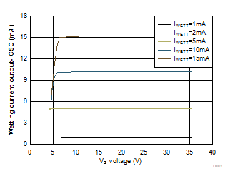
| TA = 25°C |
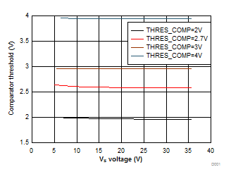
| TA = 25°C |
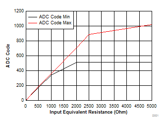
| I(WETT) = 2 mA | 6.5 V ≤ VS ≤ 35 V |
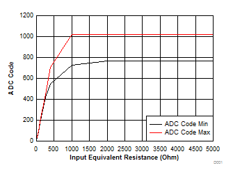
| I(WETT) = 10 mA | 6.5 V ≤ VS ≤ 35 V |
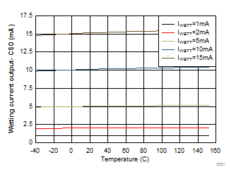
| VS = 12 V |
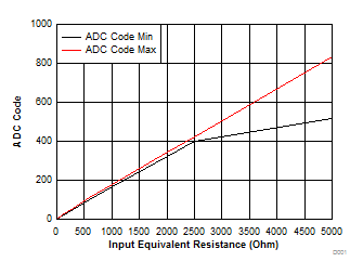
| I(WETT) = 1 mA | 6.5 V ≤ VS ≤ 35 V |
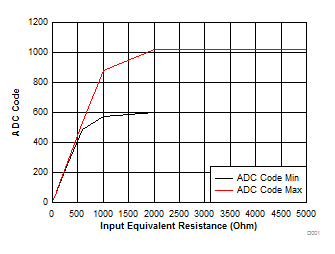
| I(WETT) = 5 mA | 6.5 V ≤ VS ≤ 35 V |
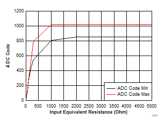
| I(WETT) = 15 mA | 6.5 V ≤ VS ≤ 35 V |
7 Parameter Measurement Information
 Figure 9. SPI Timing Parameters
 Figure 10. tREACT Timing Parameters
 Figure 11. tSO(DIS) Timing Parameters