-
TLC2274-HT Advanced LinCMOS™ Rail-to-Rail Operational Amplifier
- 1 Features
- 2 Applications
- 3 Description
- 4 Revision History
- 5 Pin Configuration and Functions
-
6 Specifications
- 6.1 Absolute Maximum Ratings
- 6.2 ESD Ratings
- 6.3 Recommended Operating Conditions
- 6.4 Thermal Information
- 6.5 Electrical Characteristics, VDD = 5 V
- 6.6 Operating Characteristics, VDD = 5 V
- 6.7 Electrical Characteristics, VDD± = ±5 V
- 6.8 Operating Characteristics, VDD± = ±5 V
- 6.9 Typical Characteristics
- 7 Detailed Description
- 8 Application and Implementation
- 9 Power Supply Recommendations
- 10Layout
- 11Device and Documentation Support
- 12Mechanical, Packaging, and Orderable Information
- IMPORTANT NOTICE
TLC2274-HT Advanced LinCMOS™ Rail-to-Rail Operational Amplifier
1 Features
- Qualified for Automotive Applications
- Qualified in Accordance With AEC-Q100
- Output Swing Includes Both Supply Rails
- Low Noise: 9 nV/√Hz Typ at ƒ = 1 kHz
- Low Input Bias Current: 1 pA Typical
- Fully Specified for Both Single-Supply and Split-Supply Operation
- Common-Mode Input Voltage Range Includes Negative Rail
- High-Gain Bandwidth: 2.2 MHz Typical
- High Slew Rate: 3.6 V/μs Typical
- Low Input Offset Voltage 2500-μV Max at TA = 25°C
- Macromodel Included
2 Applications
- Supports Extreme Temperature Applications:
- Controlled Baseline
- One Assembly and Test Site
- One Fabrication Site
- Available in Extreme (–40°C to 150°C) Temperature Range (1)
- Extended Product Life Cycle
- Extended Product-Change Notification
- Product Traceability
- Texas Instruments' high temperature products use highly-optimized silicon (die) solutions with design and process enhancements to maximize performance over extended temperatures. All devices are characterized and qualified for 1000 hours continuous operating life at maximum rated temperature.
3 Description
The TLC2274 is a quadruple operational amplifier from Texas Instruments. The device exhibits rail-to-rail output performance for increased dynamic range in single- or split-supply applications. The TLC2274 offers 2 MHz of bandwidth and 3 V/μs of slew rate for higher speed applications. These device offers comparable ac performance while having better noise, input offset voltage, and power dissipation than existing CMOS operational amplifiers. The TLC2274 has a noise voltage of 9nV/√Hz, two times lower than competitive solutions.
The TLC2274, exhibiting high input impedance and low noise, is excellent for small-signal conditioning for high-impedance sources, such as piezoelectric transducers. Because of the micropower dissipation levels, this device works well in hand-held monitoring and remote-sensing applications. In addition, the rail-to-rail output feature, with single- or split-supplies, makes this device a great choice when interfacing with analog-to-digital converters (ADCs). This family is fully characterized at 5 V and ±5 V.
It offers increased output dynamic range, lower noise voltage, and lower input offset voltage. This enhanced feature set allows the device to be used in a wider range of applications.
Device Information(1)
| PART NUMBER | PACKAGE | BODY SIZE (NOM) |
|---|---|---|
| TLC2274-HT | TSSOP (14) | 6.60 mm × 5.10 mm |
- For all available packages, see the orderable addendum at the end of the data sheet.
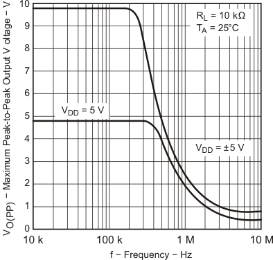
Maximum Peak-to-Peak Output Voltage
vs Supply Voltage

4 Revision History
| DATE | REVISION | NOTES |
|---|---|---|
| January 2015 | * | Initial release. |
5 Pin Configuration and Functions
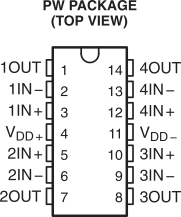
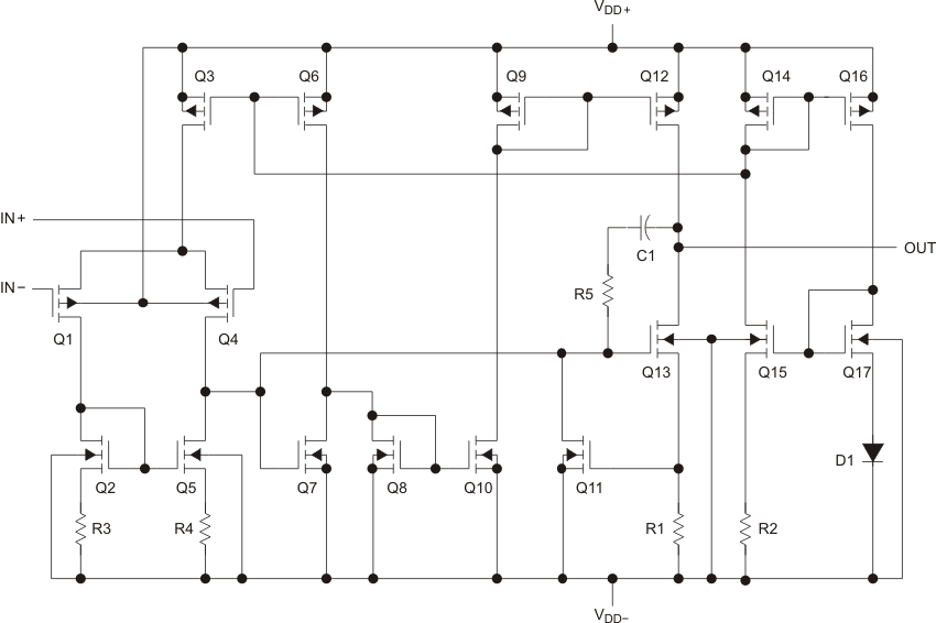 Figure 1. Equivalent Schematic (Each Amplifier)
Table 1. Actual Device Component Count(1)
| COMPONENT | TLC2274 |
|---|---|
| Transistors | 76 |
| Resistors | 52 |
| Diodes | 18 |
| Capacitors | 6 |
6 Specifications
6.1 Absolute Maximum Ratings(1)
over operating free-air temperature range (unless otherwise noted)| MIN | MAX | UNIT | |||
|---|---|---|---|---|---|
| VDD+ | Supply voltage(2) | 8 | V | ||
| VDD– | Supply voltage(2) | –8 | V | ||
| VID | Differential input voltage(3) | –16 | 16 | V | |
| VI | Input voltage(2) | Any input | VDD– – 0.3 | VDD+ | V |
| II | Input current | Any input | –5 | 5 | mA |
| IO | Output current | –50 | 50 | mA | |
| Total current into VDD+ | –50 | 50 | mA | ||
| Total current out of VDD− | –50 | 50 | mA | ||
| Duration of short-circuit current at (or below) 25°C(4) | Unlimited | ||||
| TA | Operating free-air temperature | –40 | 150 | °C | |
| Lead temperature 1.6 mm (1/16 inch) from case for 10 s | 260 | °C | |||
| Tstg | Storage temperature | –65 | 150 | °C | |
6.2 ESD Ratings
| VALUE | UNIT | ||||
|---|---|---|---|---|---|
| V(ESD) | Electrostatic discharge | Human-body model (HBM), per AEC Q100-002(1) | ±2500 | V | |
| Charged-device model (CDM), per AEC Q100-011 | All pins | ±1500 | |||
6.3 Recommended Operating Conditions
over operating free-air temperature range (unless otherwise noted)| MIN | MAX | UNIT | ||
|---|---|---|---|---|
| VDD± | Supply voltage | ±2.2 | ±8 | V |
| VI | Input voltage | VDD− | VDD+ −1.5 | V |
| VIC | Common-mode input voltage | VDD− | VDD+ −1.5 | V |
| TA | Operating free-air temperature | −40 | 150 | °C |
6.4 Thermal Information
| THERMAL METRIC(1) | TLC2274 | UNIT | |
|---|---|---|---|
| PW | |||
| 14 PINS | |||
| RθJA | Junction-to-ambient thermal resistance | 106.0 | °C/W |
| RθJC(top) | Junction-to-case (top) thermal resistance | 35.5 | |
| RθJB | Junction-to-board thermal resistance | 47.6 | |
| ψJT | Junction-to-top characterization parameter | 2.4 | |
| ψJB | Junction-to-board characterization parameter | 47.1 | |
6.5 Electrical Characteristics, VDD = 5 V
at specified free-air temperature, VDD = 5 V (unless otherwise noted)| PARAMETER | TEST CONDITIONS | TA(1) | MIN | TYP | MAX | UNIT | ||
|---|---|---|---|---|---|---|---|---|
| VIO | Input offset voltage | VIC = 0 V, VO = 0 V, |
VDD± = ±2.5 V, RS = 50 Ω |
25°C | 300 | 2500 | μV | |
| Full range | 3000 | |||||||
| αVIO | Temperature coefficient of input offset voltage | 25°C to 125°C | 2 | μV/°C | ||||
| Input offset voltage long-term drift(2) | 25°C | 0.002 | μV/mo | |||||
| IIO | Input offset current | 25°C | 0.5 | 60 | pA | |||
| Full range | 7000 | |||||||
| IIB | Input bias current | 25°C | 1 | pA | ||||
| Full range | ||||||||
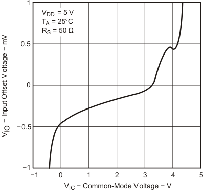
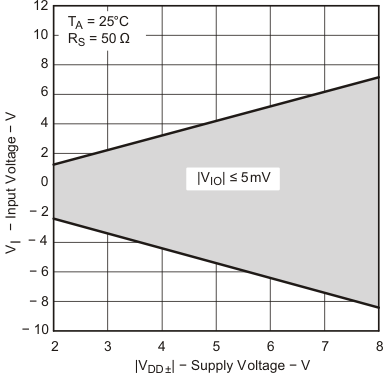
| VICR | Common-mode input voltage range | RS = 50 Ω | |VIO| ≤ 5 mV | 25°C | 0 to 4 | −0.3 to 4.2 | V | |
| Full range | 0 to 3.5 | |||||||
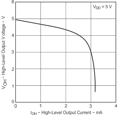
| VOH | High-level output voltage | IOH = −20 μA | 25°C | 4.99 | V | |||
| IOH = −200 μA | 25°C | 4.85 | 4.93 | |||||
| Full range | 4.84 | |||||||
| IOH = −1 mA | 25°C | 4.25 | 4.65 | |||||
| Full range | 4.20 | |||||||
| VOL | Low-level output voltage | VIC = 2.5 V, | IOL = 50 μA | 25°C | 0.01 | V | ||
| VIC = 2.5 V, | IOL = 500 μA | 25°C | 0.09 | 0.15 | ||||
| Full range | 0.16 | |||||||
| VIC = 2.5 V, | IOL = 5 mA | 25°C | 0.9 | 1.5 | ||||
| Full range | 1.6 | |||||||
| AVD | Large-signal differential voltage amplification | VIC = 2.5 V, VO = 1 V to 4 V, |
RL = 10 kΩ(3) | 25°C | 10 | 35 | V/mV | |
| Full range | 8 | |||||||
| RL = 1 MΩ(3) | 25°C | 175 | ||||||
| rid | Differential input resistance | 25°C | 1012 | Ω | ||||
| ri | Common-mode input resistance | 25°C | 1012 | Ω | ||||
| ci | Common-mode input capacitance | f = 10 kHz, | N package | 25°C | 8 | pF | ||
| zo | Closed-loop output impedance | f = 1 MHz, | AV = 10 | 25°C | 140 | Ω | ||
| CMRR | Common-mode rejection ratio | VIC = 0 V to 2.7 V, VO = 2.5 V, |
RS = 50 Ω | 25°C | 70 | 75 | dB | |
| Full range | 69 | |||||||
| kSVR | Supply voltage rejection ratio (ΔVDD/ΔVIO) | VDD = 4.4 V to 16 V, | 25°C | 80 | 95 | dB | ||
| VIC = VDD/2, | No load | Full range | 80 | |||||
| IDD | Supply current | VO = 2.5 V, | No load | 25°C | 4.4 | 6 | mA | |
| Full range | 6 | |||||||
6.6 Operating Characteristics, VDD = 5 V
at specified free-air temperature, VDD = 5 V (unless otherwise noted)| PARAMETER | TEST CONDITIONS | TA(1) | MIN | TYP | MAX | UNIT | ||
|---|---|---|---|---|---|---|---|---|
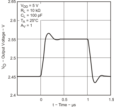
| SR | Slew rate at unity gain | VO = 0.5 V to 2.5 V, CL = 100 pF(2) |
RL = 10 kΩ(2) | 25°C | 2.3 | 3.6 | V/μs | |
| Full range | 1.2 | |||||||
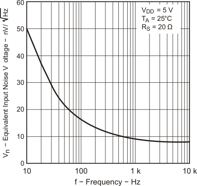
| Vn | Equivalent input noise voltage | f = 10 Hz | 25°C | 50 | nV/√Hz | |||
| f = 1 kHz | 25°C | 9 | ||||||
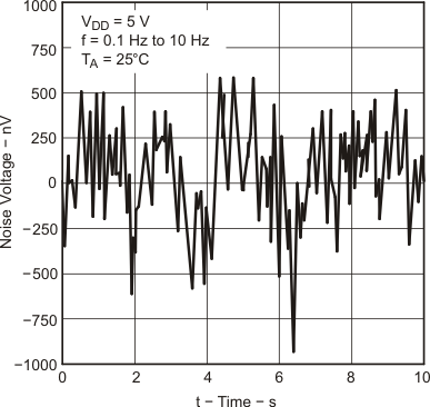
| VN(pp) | Peak-to-peak equivalent input noise voltage | f = 0.1 to 1 Hz | 25°C | 1 | μV | |||
| f = 0.1 to 10 Hz | 25°C | 1.4 | ||||||
| In | Equivalent input noise current | 25°C | 0.6 | fA/√Hz | ||||
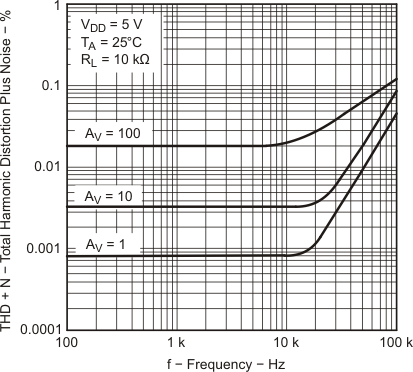
| THD + N | Total harmonic distortion plus noise | VO = 0.5V to 2.5V, RL = 10 kΩ, f = 20 kHz (2) |
AV = 1 | 25°C | 0.0013% | |||
| AV = 10 | 0.004% | |||||||
| AV = 100 | 0.03% | |||||||
| Gain-bandwidth product | f = 10 kHz, CL = 100 pF(2) |
RL = 10 kΩ(2) | 25°C | 2.18 | MHz | |||
| BOM | Maximum output-swing bandwidth | VO(PP) = 2V, RL = 10 kΩ(2) |
AV = 1, CL = 100 pF(2) |
25°C | 1 | MHz | ||
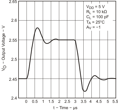
| ts | Settling time | AV = -1, Step = 0.5V to 2.5V, RL = 10 kΩ(2) CL = 100 pF(2) |
To 0.1% | 25°C | 1.5 | μs | ||
| To 0.01% | 2.6 | |||||||
| φm | Phase margin at unity gain | RL = 10 kΩ | CL = 100 pF(2) | 25°C | 50° | |||
| Gain margin | 25°C | 10 | dB | |||||
6.7 Electrical Characteristics, VDD± = ±5 V
at specified free-air temperature, VDD± = ±5 V (unless otherwise noted)| PARAMETER | TEST CONDITIONS | TA(1) | MIN | TYP | MAX | UNIT | ||
|---|---|---|---|---|---|---|---|---|
| VIO | Input offset voltage | VIC = 0 V, RS = 50 Ω |
VO = 0 V | 25°C | 300 | 2500 | μV | |
| Full range | 3000 | |||||||
| αVIO | Temperature coefficient of input offset voltage | 25°C to 125°C | 2 | μV/°C | ||||
| Input offset voltage long-term drift(2) | 25°C | 0.002 | μV/mo | |||||
| IIO | Input offset current | 25°C | 0.5 | 60 | pA | |||
| Full range | 7000 | |||||||
| IIB | Input bias current | 25°C | 1 | 60 | pA | |||
| Full range | 7000 | |||||||
| VICR | Common-mode input voltage range | RS = 50 Ω | |VIO| ≤ 5 mV | 25°C | −5 to 4 | −5.3 to 4.2 | V | |
| Full range | −5 to 3.5 | |||||||
| VOM+ | Maximum positive peak output voltage | IO = −20 μA | 25°C | 4.99 | V | |||
| IO = −200 μA | 25°C | 4.85 | 4.93 | |||||
| Full range | 4.84 | |||||||
| IO = −1 mA | 25°C | 4.25 | 4.65 | |||||
| Full range | 4.20 | |||||||
| VOM- | Maximum negative peak output voltage | VIC = 0 V, | IO = 50 μA | 25°C | −4.99 | V | ||
| VIC = 0 V, | IO = 500 μA | 25°C | −4.85 | −4.91 | ||||
| Full range | −4.85 | |||||||
| VIC = 0 V, | IO = 5 mA | 25°C | −3.5 | −4.1 | ||||
| Full range | −3.45 | |||||||
| AVD | Large-signal differential voltage amplification | VO = ±4 V, | RL = 10 kΩ | 25°C | 20 | 50 | V/mV | |
| Full range | 16 | |||||||
| RL = 1 MΩ | 25°C | 300 | ||||||
| rid | Differential input resistance | 25°C | 1012 | Ω | ||||
| ri | Common-mode input resistance | 25°C | 1012 | Ω | ||||
| ci | Common-mode input capacitance | f = 10 kHz, | N package | 25°C | 8 | pF | ||
| zo | Closed-loop output impedance | f = 1 MHz, | AV = 10 | 25°C | 130 | Ω | ||
| CMRR | Common-mode rejection ratio | VIC = -5 V to 2.7 V, VO = 0 V, |
RS = 50 Ω | 25°C | 75 | 80 | dB | |
| Full range | 73 | |||||||
| kSVR | Supply voltage rejection ratio (ΔVDD/ΔVIO) | VDD = ±2.2 V to ±8 V, | 25°C | 80 | 95 | dB | ||
| VIC = 0V, | No load | Full range | 80 | |||||
| IDD | Supply current | VO = 0 V, | No load | 25°C | 4.4 | 6 | mA | |
| Full range | 6 | |||||||
6.8 Operating Characteristics, VDD± = ±5 V
at specified free-air temperature, VDD± = ±5 V (unless otherwise noted)| PARAMETER | TEST CONDITIONS | TA(1) | MIN | TYP | MAX | UNIT | ||
|---|---|---|---|---|---|---|---|---|
| SR | Slew rate at unity gain | VO = ±2.3 V, RL = 10 kΩ |
CL = 100 pF | 25°C | 2.3 | 3.6 | V/μs | |
| Full range | 1.2 | |||||||
| Vn | Equivalent input noise voltage | f = 10 Hz | 25°C | 50 | nV/√Hz | |||
| f = 1 kHz | 25°C | 9 | ||||||
| VN(pp) | Peak-to-peak equivalent input noise voltage | f = 0.1 to 1 Hz | 25°C | 1 | μV | |||
| f = 0.1 to 10 Hz | 25°C | 1.4 | ||||||
| In | Equivalent input noise current | 25°C | 0.6 | fA/√Hz | ||||
| THD + N | Total harmonic distortion plus noise | VO = ±2.3 V, f = 20 kHz, RL = 10 kΩ |
AV = 1 | 25°C | 0.0011% | |||
| AV = 10 | 0.004% | |||||||
| AV = 100 | 0.03% | |||||||
| Gain-bandwidth product | f = 10 kHz, CL = 100 pF |
RL = 10 kΩ | 25°C | 2.25 | MHz | |||
| BOM | Maximum output-swing bandwidth | VO(PP) = 4.6 V, RL = 10 kΩ |
AV = 1, CL = 100 pF |
25°C | 0.54 | MHz | ||
| ts | Settling time | AV = -1, Step = -2.3 V to 2.3 V, RL = 10 kΩ CL = 100 pF |
To 0.1% | 25°C | 1.5 | μs | ||
| To 0.01% | 3.2 | |||||||
| φm | Phase margin at unity gain | RL = 10 kΩ, | CL = 100 pF | 25°C | 52° | |||
| Gain margin | 25°C | 10 | dB | |||||
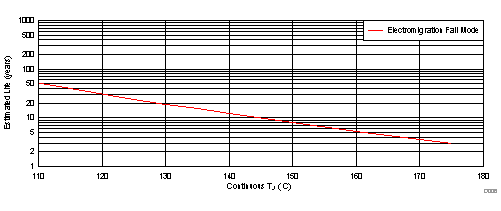
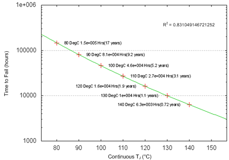 Figure 3. Estimated Wire Bond Life
6.9 Typical Characteristics
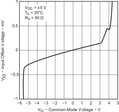
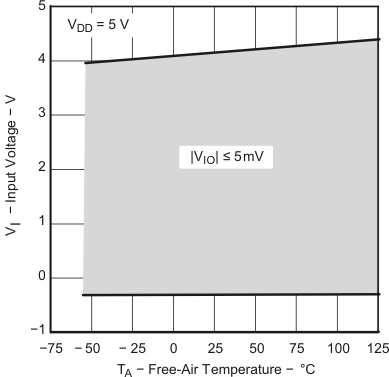
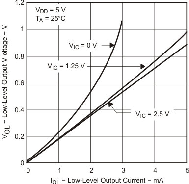
Data at high and low temperatures are applicable only within the rated operating free-air temperature ranges of the devices.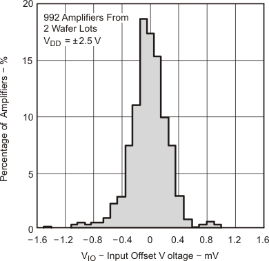
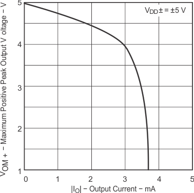
| TA = 25°C |
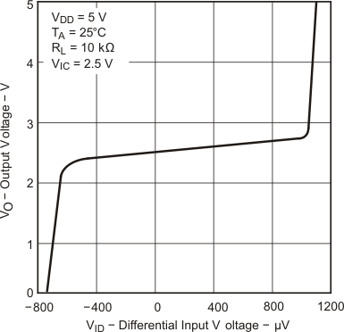
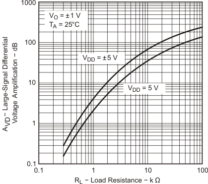
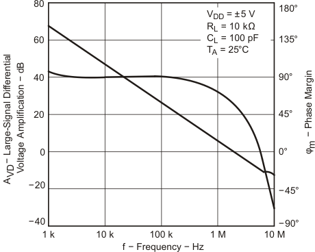
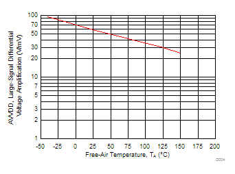
| VDD = ±5 V | VIC = 2.5 V | VO = ±4 V |
| RL = 10 kΩ |
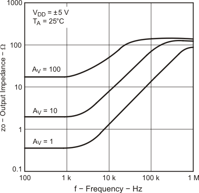
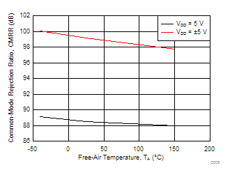
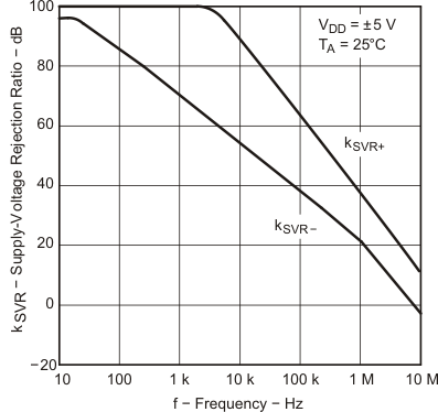
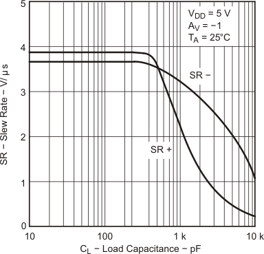
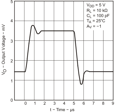
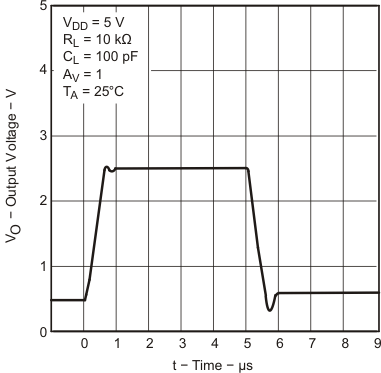
| TA = 25°C |
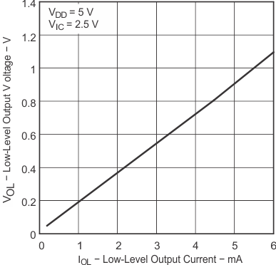
| TA = 25°C |
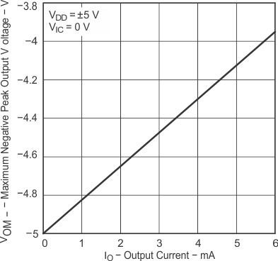
| TA = 25°C |
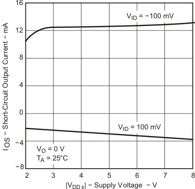
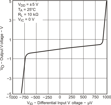
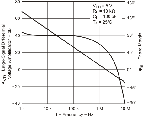
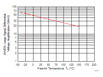
| VDD = 5 V | VIC = 2.5 V | VO = 1 to 4 V |
| RL = 10 kΩ |
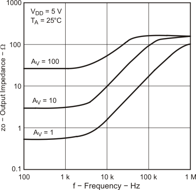
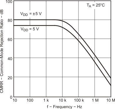
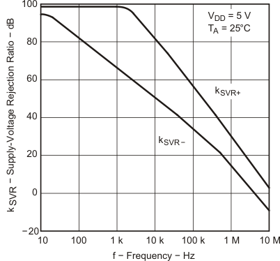
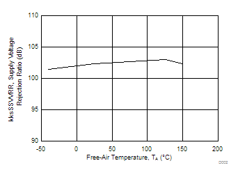
| VDD± = ±2.2 to ±8 V | VO = 0 V |
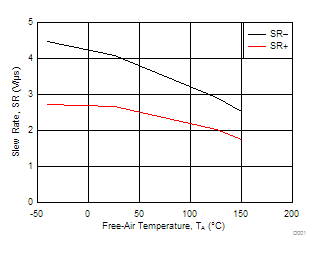
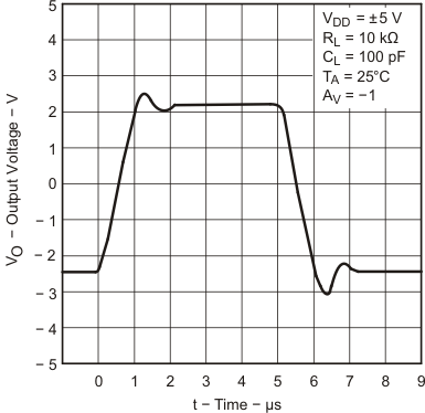
| VDD = 5 V | RL = 10 kΩ | CL = 100 pF |
| AV = 1 |
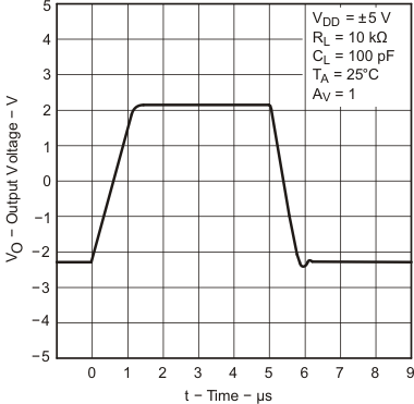
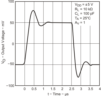
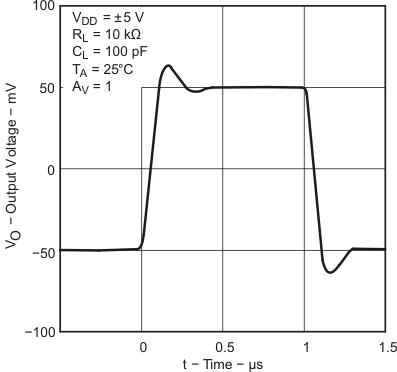
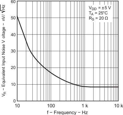
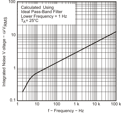
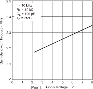
7 Detailed Description
7.1 Overview
The TLC2274 device exhibits rail-to-rail output performance for increased dynamic range in single- or split -supply applications. These device offers comparable ac performance while having better noise, input offset voltage and power dissipation than existing CMOS operational amplifiers. The TLC2274 device, exhibiting high input impedance and low noise, is excellent for small signal conditioning for high-impedance sources, such as piezoelectric transducers. It offers increased output dynamic range, lower noise voltage, and lower input offset voltage. This enhanced feature set allows the device to be used in a wider range of applications.
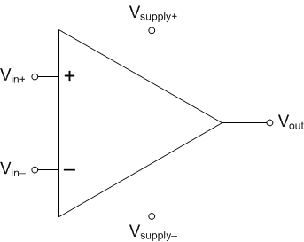
7.2 Functional Block Diagram
7.3 Feature Description
These devices use the Texas Instruments silicon gate LinCMOS™ process, giving them stable input offset voltages, very high input impedances, and extremely low input offset and bias currents. In addition, the rail-to-rail output feature with single- or split-supplies, makes this device a great choice when interfacing with analog-to-digital converters (ADCs).
8 Application and Implementation
NOTE
Information in the following applications sections is not part of the TI component specification, and TI does not warrant its accuracy or completeness. TI’s customers are responsible for determining suitability of components for their purposes. Customers should validate and test their design implementation to confirm system functionality.
8.1 Application Information
8.1.1 Macromodel Information
Macromodel information provided was derived using Microsim Parts, the model generation software used with Microsim PSpice. The Boyle macromodel
- Maximum positive output voltage swing
- Maximum negative output voltage swing
- Slew rate
- Quiescent power dissipation
- Input bias current
- Open-loop voltage amplification
- Unity-gain frequency
- Common-mode rejection ratio
- Phase margin
- DC output resistance
- AC output resistance
- Short-circuit output current limit
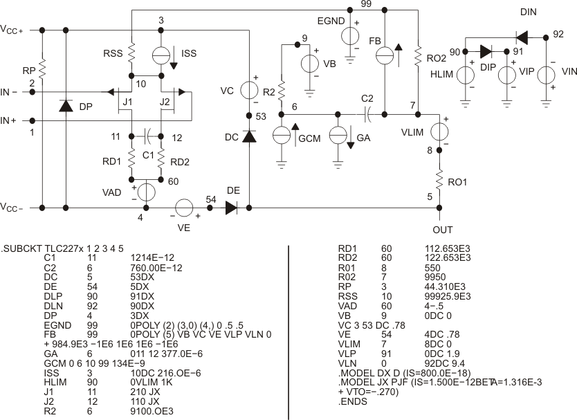 Figure 46. Boyle Macromodels and Subcircuit
8.2 Typical Application
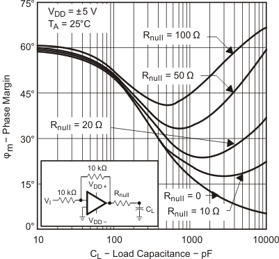
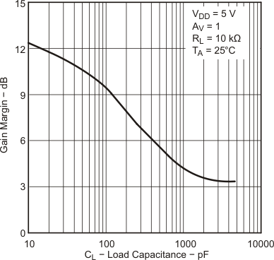
The TLC2274 is designed to drive larger capacitive loads than most CMOS operational amplifiers. Figure 48 and Figure 49 show its ability to drive loads up to 1000 pF while maintaining good gain and phase margins (Rnull = 0).
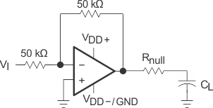 Figure 47. Typical Application Schematic
8.2.1 Design Requirements
As per Equation 1:
Table 2. Design Parameters
| Improvement in Phase Margin | UGBW (kHz) | R null (Ω) | CL (pF) |
|---|---|---|---|
| 0 | 1000 | 0 | 1000 |
| 7.15 | 1000 | 20 | 1000 |
| 17.43 | 1000 | 50 | 1000 |
| 32.12 | 1000 | 100 | 1000 |
8.2.2 Detailed Design Procedure
A smaller series resistor (Rnull) at the output of the device (see Figure 47) improves the gain and phase margins when driving large capacitive loads. Figure 48 and Figure 49 show the effects of adding series resistances of 10 Ω, 50 Ω, 100 Ω, 200 Ω, and 500 Ω. The addition of this series resistor has two effects: the first is that it adds a zero to the transfer function and the second is that it reduces the frequency of the pole associated with the output load in the transfer function.
The zero introduced to the transfer function is equal to the series resistance times the load capacitance. To calculate the improvement in phase margin, Equation 1 can be used.
where
- Δφm1 = Improvement in phase margin
- UGBW = Unity-gain bandwidth frequency
- Rnull = Output series resistance
- CL = Load capacitance
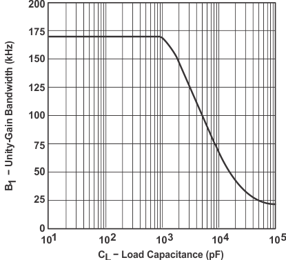
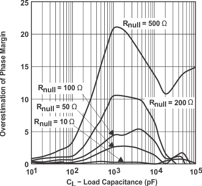
The unity-gain bandwidth (UGBW) frequency decreases as the capacitive load increases (see Figure 47). To use equation 1, UGBW must be approximated from Figure 47. Using Equation 1 alone overestimates the improvement in phase margin, as illustrated in Figure 51. The overestimation is caused by the decrease in the frequency of the pole associated with the load, thus providing additional phase shift and reducing the overall improvement in phase margin. Using Figure 47, with Equation 1 enables the designer to choose the appropriate output series resistance to optimize the design of circuits driving large capacitance loads.
8.2.3 Application Curves
TA = 25°C