JAJSC75 May 2016 TLC6C598
PRODUCTION DATA.
- 1 特長
- 2 アプリケーション
- 3 概要
- 4 改訂履歴
- 5 Pin Configuration and Functions
- 6 Specifications
- 7 Parameter Measurement Information
- 8 Detailed Description
- 9 Application and Implementation
- 10Power Supply Recommendations
- 11Layout
- 12デバイスおよびドキュメントのサポート
- 13メカニカル、パッケージ、および注文情報
11 Layout
11.1 Layout Guidelines
There are no special layout requirements for the digital signal pins. The only requirement is placing the ceramic bypass capacitors near the corresponding pins.
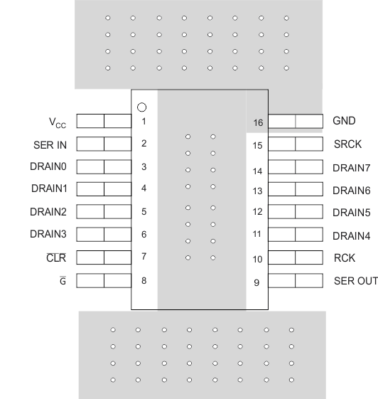
Maximize the copper coverage on the PCB to increase the thermal conductivity of the board. The major heat-flow path from the package to the ambient is through the copper on the PCB. Maximizing the copper coverage is extremely important when the design does not include heat sinks attached to the PCB on the other side of the package.
Add as many thermal vias as possible directly under the package ground pad to optimize the thermal conductivity of the board.
All thermal vias should be either plated shut or plugged and capped on both sides of the board to prevent solder voids. To ensure reliability and performance, the solder coverage should be at least 85%.
11.2 Layout Example
 Figure 16. TLC6C598 Example Layout