-
TMDS181x 6 Gbps TMDS Retimer
- 1 Features
- 2 Applications
- 3 Description
- 4 Revision History
- 5 Pin Configuration and Functions
-
6 Specifications
- 6.1 Absolute Maximum Ratings
- 6.2 ESD Ratings
- 6.3 Recommended Operating Conditions
- 6.4 Thermal Information
- 6.5 Power Supply Electrical Characteristics
- 6.6 TMDS Differential Input Electrical Characteristics
- 6.7 TMDS Differential Output Electrical Characteristics
- 6.8 DDC, I2C, HPD, and ARC Electrical Characteristics
- 6.9 Power-Up and Operation Timing Requirements
- 6.10 TMDS Switching Characteristics
- 6.11 HPD Switching Characteristics
- 6.12 DDC and I2C Switching Characteristics
- 6.13 Typical Characteristics
- 7 Parameter Measurement Information
-
8 Detailed Description
- 8.1 Overview
- 8.2 Functional Block Diagram
- 8.3
Feature Description
- 8.3.1 Reset Implementation
- 8.3.2 Operation Timing
- 8.3.3 Swap and Polarity Working
- 8.3.4 TMDS Inputs
- 8.3.5 TMDS Inputs Debug Tools
- 8.3.6 Receiver Equalizer
- 8.3.7 Input Signal Detect Block
- 8.3.8 Audio Return Channel
- 8.3.9 Transmitter Impedance Control
- 8.3.10 TMDS Outputs
- 8.3.11 Pre-Emphasis/De-Emphasis
- 8.4 Device Functional Modes
- 8.5 Register Maps
- 9 Application and Implementation
- 10Power Supply Recommendations
- 11Layout
- 12Device and Documentation Support
- 13Mechanical, Packaging, and Orderable Information
- IMPORTANT NOTICE
パッケージ・オプション
メカニカル・データ(パッケージ|ピン)
- RGZ|48
サーマルパッド・メカニカル・データ
- RGZ|48
発注情報
TMDS181x 6 Gbps TMDS Retimer
1 Features
- HDMI™ Input Port to Output Port With CDR Supporting Up to 6 Gbps Data Rates
- Compatible With HDMI™ Electrical Parameters Up to 6 Gbps in Retimer Mode
- Support 4k2k60p and Up to WUXGA 16-Bit Color Depth or 1080p With Higher Refresh Rates
- Retimes Input Stream to Compensate for Random Jitter
- Adaptive Receiver Equalizer or Programmable Fixed Equalizer
- I2C and Pin Strap Programmable
- Inter-Pair Skew Compensation of 5+ Bits
- Single-Ended Mode ARC Support
- Link Debug Tools Including Eye Diagram After the RX Equalizer
- 48-Pin 7-mm × 7-mm 0.5-mm Pitch VQFN Package
- Extended Commercial Temperature Support 0°C to 85°C (TMDS181)
- Industrial Temperature Support: –40°C to 85°C (TMDS181I)
2 Applications
- Digital TV
- Digital Projector
- Audio/Video Equipment
- Blu-ray™ DVD
- Monitors
- Desktops/ All-in-Ones
- Active Cables
3 Description
The TMDS181x is a digital video interface (DVI) or high-definition multimedia interface (HDMI™) retimer. The TMDS181x supports four TMDS channels, audio return channel (SPDIF_IN/ARC_OUT), and digital display control (DDC) interfaces. The TMDS181x supports signaling rates up to 6 Gbps to allow for the highest resolutions of 4k2k60p 24 bits per pixel and up to WUXGA 16-bit color depth or 1080p with higher refresh rates. The TMDS181x can be configured to support the HDMI2.0a standard. The TMDS181x automatically configures itself as a redriver at low data rate (<1.0 Gbps) or as a retimer above this data rate. Redriver mode supports HDMI1.4b with data rates up to 3.4 Gbps
The TMDS181x supports dual power supply rails of 1.2 V on VDD and 3.3 V on VCC for power reduction. Several methods of power management are implemented to reduce overall power consumption. TMDS181x supports fixed receive EQ gain or adaptive receive EQ control by I2C or pin strap to compensate for different lengths input cable or board traces.
Device Information(1)
| PART NUMBER | PACKAGE | BODY SIZE (NOM) |
|---|---|---|
| TMDS181 | VQFN (48) | 7.00 mm × 7.00 mm |
| TMDS181I |
- For all available packages, see the orderable addendum at the end of the data sheet.
SPACE
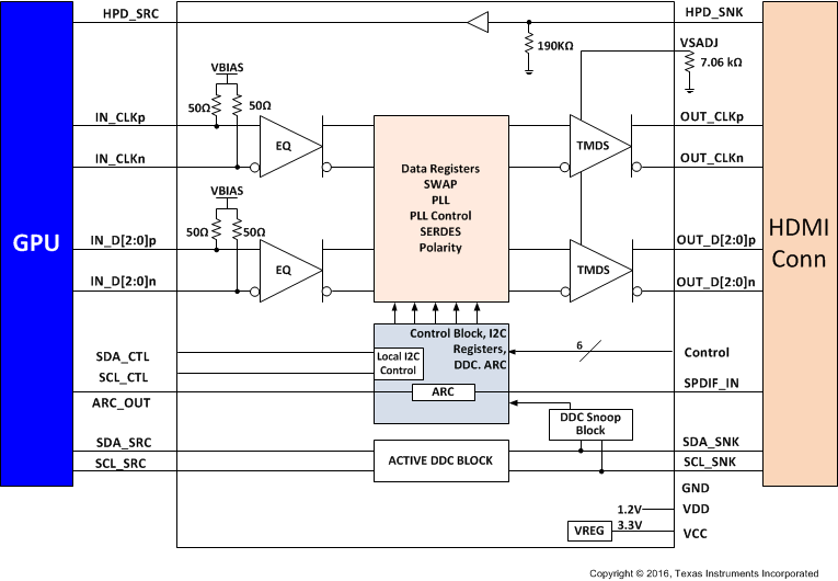
Simplified Schematic

4 Revision History
Changes from C Revision (July 2016) to D Revision
- Added Note 5 to the Power Supply Electrical Characteristic table Go
- Deleted text "which is needed for certain HDMI CTS test." from the third paragraph in the Overview section Go
- Changed section: Input Signal Detect Block Go
- Changed H to X in the first row of the HPD_SNK column in Table 12Go
- Changed the IN_Dx column in Table 12 Go
Changes from B Revision (April 2016) to C Revision
- Recommended Operating Conditions, Changed the CONTROL PINS section Go
- DDC, I2C, HPD, and ARC Electrical Characteristics, Changed the DDC AND I2C sectionGo
Changes from A Revision (October 2015) to B Revision
- Recommended Operating Conditions, Added VIL "Low-level input voltage at HPD, OE"Go
- Recommended Operating Conditions, Moved pin OE From: VIH MIN value of 2 V To: VIH MIN value of 2.6 V Go
- Power-Up and Operation Timing Requirements, Deleted the VDD_ramp and VCC_ramp MIN values Go
- Changed Figure 1 Go
- DDC Functional Description, Changed text "address 22h (see Figure 31) through the I2C interface." To: "address 0Bh through the I2C interface."Go
- Added Note to 11–400-kbps in Table 6Go
- Added Note to 11–400-kbps in Table 6Go
Changes from * Revision (August 2015) to A Revision
- Updated device from product preview to production data Go
- Absolute Maximum Ratings, Changed max value from 1.56 V to VCC + 0.3V; added input current and Min valueGo
- Absolute Maximum Ratings, Added Max Input Current on Main Link Differential Input pinsGo
- Recommended Operating Conditions, Updated the note showing the values shown are only for Microcontroller driven and not values based upon pull up or pull down resistors. Go
- Power Supply Electrical Characteristics, Increased Max Value of ISD2 from 10 to 15mA Go
- TMDS Differential Input Electrical Characteristics, Changed Max Receiver impedance value to 115 Go
- DDC, I2C, HPD, and ARC Electrical Characteristics, Inserted values for SCL/SDA_SNK Go
- TMDS Switching Characteristics, Changed from 6000 to 3400 Go
- Table 4, Deleted Clear and NA Access Tags Go
- Table 8, Removed reg20h[5:4] ARC_SWING Go
- Figure 35, Removed 1k pullup from switch as not needed Go
- Pin Strapping Configuration for HDMI2.0a and HDMI1.4b, Added Note for VSADJ resistor value in Compliance Pin Strapping section Go
- Pin Strapping Configuration for HDMI2.0a and HDMI1.4b, Changed De-emphasis value from 0 dB to -2 dB for recommended configuration for compliance testing.Go
- I2C Control for HDMI2.0a and HDMI1.4b, Added Note for VSADJ resistor value in Compliance I2C control section and included register that can increase or decrease the VOD swing Go
5 Pin Configuration and Functions
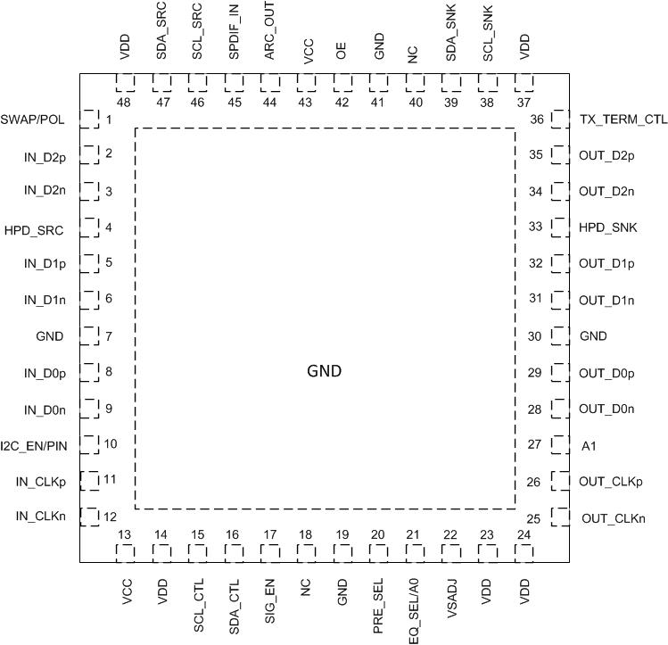
Pin Functions(2)
| PIN | TYPE(1) | DESCRIPTION | |
|---|---|---|---|
| NAME | NO. | ||
| VCC | 13, 43 | P | 3.3 V power supply |
| VDD | 14, 23, 24, 37, 48 | P | 1.2 V power supply |
| GND | 7, 19, 41, 30, Thermal pad |
G | Ground |
| MAIN LINK INPUT PINS | |||
| IN_D2p/n | 2, 3 | I | Channel 2 differential input |
| IN_D1p/n | 5, 6 | I | Channel 1 differential input |
| IN_D0p/n | 8, 9 | I | Channel 0 differential input |
| IN_CLKp/n | 11, 12 | I | Clock differential input |
| MAIN LINK OUTPUT PINS (FAIL SAFE) | |||
| OUT_D2n/p | 34, 35 | O | TMDS data 2 differential output |
| OUT_D1n/p | 31, 32 | O | TMDS data 1 differential output |
| OUT_D0n/p | 28, 29 | O | TMDS data 0 differential output |
| OUT_CLKn/p | 25, 26 | O | TMDS data clock differential output |
| HOT PLUG DETECT PINS | |||
| HPD_SRC | 4 | O | Hot plug detect output to source side |
| HPD_SNK | 33 | I | Hot plug detect input from sink side |
| AUDIO RETURN CHANNEL AND DDC PINS | |||
| SPDIF_IN ARC_OUT |
45 44 |
I/O | SPDIF signal input Audio return channel output |
| SDA_SRC SCL_SRC |
47 46 |
I/O | Source side TMDS port bidirectional DDC data line Source side TMDS port bidirectional DDC clock line |
| SDA_SNK SCL_SNK |
39 38 |
I/O | Sink side TMDS port bidirectional DDC data line Sink side TMDS port bidirectional DDC clock line |
| CONTROL PINS | |||
| OE | 42 | I | Operation enable/reset pin OE = L: Power-down mode OE = H: Normal operation Internal weak pull up: Resets device when transitions from H to L |
| SIG_EN | 17 | I | Signal detector circuit enable SIG_EN = L: Signal detect circuit disabled: SIG_EN = H: Signal detect circuit enabled: When no valid clock device enters standby mode. Internal weak pull down |
| PRE_SEL | 20 | I 3 level |
De-emphasis control when I2C_EN/PIN = Low. PRE_SEL = L: –2 dB PRE_SEL = No Connect: 0 dB PRE_SEL = H: Reserved When I2C_EN/PIN = High de-emphasis is controlled through I2C |
| EQ_SEL/A0 | 21 | I 3 level |
Input receive equalization pin strap when I2C_EN/PIN = Low EQ_SEL = L: Fixed EQ at 7.5 dB at 3 GHz EQ_SEL = No Connect: Adaptive EQ EQ_SEL = H: Fixed at 14 dB at 3 GHz When I2C_EN/PIN = High address bit 1 Note: 3 level for pin strap programming but 2 level when I2C address |
| I2C_EN/PIN | 10 | I | I2C_EN/PIN = High; puts device into I2C Control Mode I2C_EN/PIN = Low; puts device into pin strap mode Note: I2C CSR is addressable at all times, but features that can be controlled by pin strapping can only be changed by I2C when this pin is pulled high |
| SCL_CTL | 15 | I | I2C clock signal Note: When I2C_EN = Low Pin strapping takes priority and those functions cannot be changed by I2C |
| SDA_CTL | 16 | I/0 | I2C data signal Note: When I2C_EN = Low Pin strapping takes priority and those functions cannot be changed by I2C |
| VSadj | 22 | I | TMDS-compliant voltage swing control nominal resistor to GND |
| A1 | 27 | I | High address bit 2 for I2C programming Weak internal pull down Note: When in Pin Strapping Mode leave pin as No connect |
| TX_TERM_CTL | 36 | I 3 level |
Transmit termination control TX_TERM_CTL = H, no transmit termination TX_TERM_CTL = L, transmit termination impedance in approximately 75 to 150 Ω TX_TERM_CTL = No Connect, automatically selects the termination impedance Data rate (DR) > 3.4 Gbps – 75 to 150 Ω differential near end termination 2 Gbps > DR < 3.4 Gbps – 150 to 300 Ω differential near end termination DR < 2 Gbps – no termination Note: If left floating will be in automatic select mode. |
| SWAP/POL | 1 | I 3 level |
Input lane SWAP and polarity control pin SWAP/POL = H: receive lanes polarity swap (retimer mode only) SWAP/POL = L: receive lanes swap (redriver and retimer mode) SWAP/POL = No Connect: normal operation |
| NC | 18, 40 | NA | No connect |
6 Specifications
6.1 Absolute Maximum Ratings
over operating free-air temperature range (unless otherwise noted) (1)(2)| MIN | MAX | UNIT | ||
|---|---|---|---|---|
| Supply voltage(3) | VCC | –0.3 | 4 | V |
| VDD | –0.3 | 1.4 | ||
| Voltage | Main link input differential voltage (IN_Dx, IN_CLKx) IIN = 15mA | VCC - 0.75V | VCC + 0.3V | V |
| TMDS outputs ( OUT_Dx) | –0.3 | 4 | ||
| HPD_SRC, Vsadj, SDA_CTL, SCL_CTL, OE, A1, PRE_SEL, EQ_SEL/A0, I2C_EN/PIN, SIG_EN, TX_TERM_CTL, | –0.3 | 4 | ||
| HDP_SNK, SDA_SNK, SCL_SNK, SDA_SRC, SCL_SRC | –0.3 | 6 | ||
| Input Current IIN | Main link input current (IN_Dx, IN_CLKx) | 15 | mA | |
| Continuous power dissipation | See Thermal Information | |||
| Tstg | Storage temperature | –65 | 150 | °C |
6.2 ESD Ratings
| VALUE | UNIT | |||
|---|---|---|---|---|
| V(ESD) | Electrostatic discharge | Human-body model (HBM), per ANSI/ESDA/JEDEC JS-001(1) | ±2000 | V |
| Charged-device model (CDM), per JEDEC specification JESD22-C101(2) | ±500 | |||
6.3 Recommended Operating Conditions
over operating free-air temperature range (unless otherwise noted)| MIN | NOM | MAX | UNIT | |||
|---|---|---|---|---|---|---|
| VCC | Supply voltage nominal value 3.3 V | 3.135 | 3.3 | 3.465 | V | |
| VDD | Supply voltage nominal value 1.2 V | 1.1 | 1.2 | 1.27 | V | |
| TCASE | Case temperature | 92.7 | °C | |||
| TA | Operating free-air temperature | TMDS181 | 0 | 85 | °C | |
| TMDS181I | –40 | 85 | °C | |||
| MAIN LINK DIFFERENTIAL PINS | ||||||
| VID_PP | Peak-to-peak input differential voltage | 75 | 1560 | mVpp | ||
| VIC | Input common mode voltage | VCC – 0.4 | VCC + 0.1 | V | ||
| dR | Data rate | 0.25 | 6 | Gbps | ||
| RVSADJ | TMDS compliant swing voltage bias resistor nominal | 4.5 | 7.06 | kΩ | ||
| CONTROL PINS | ||||||
| VI-DC | DC input voltage | Control pins | –0.3 | 3.6 | V | |
| VIL(1) | Low-level input voltage at PRE_SEL, EQ_SEL/A0, TX_TERM_CTL, SWAP/POL pins only | 0.3 | V | |||
| Low-level input voltage at OE | 0.8 | |||||
| VIM(1) | Mid-level input voltage at PRE_SEL, EQ_SEL/A0, TX_TERM_CTL, SWAP/POL pins only | 1 | 1.2 | 1.4 | V | |
| VIH(1) | High-level input voltage at PRE_SEL, EQ_SEL/A0, TX_TERM_CTL, SWAP/POL, OE(2) pins only | 2.6 | V | |||
| VOL | Low-level output voltage | 0.4 | V | |||
| VOH | High-level output voltage | 2.4 | V | |||
| IIH | High-level input current | –30 | 30 | µA | ||
| IIL | Low-level input current | –25 | 25 | µA | ||
| IOS | Short-circuit output current | –50 | 50 | mA | ||
| IOZ | High impedance output current | 10 | µA | |||
| ROEPU | Pullup resistance on OE pin | 150 | 250 | kΩ | ||
6.4 Thermal Information
| THERMAL METRIC(1)(2) | TMDS181x | UNIT | |
|---|---|---|---|
| RGZ (VQFN) | |||
| 48 PINS | |||
| RθJA | Junction-to-ambient thermal resistance | 31.1 | °C/W |
| RθJC(top) | Junction-to-case (top) thermal resistance | 18.2 | °C/W |
| RθJB | Junction-to-board thermal resistance | 8.1 | °C/W |
| ψJT | Junction-to-top characterization parameter | 0.4 | °C/W |
| ψJB | Junction-to-board characterization parameter | 8.1 | °C/W |
| RθJC(bot) | Junction-to-case (bottom) thermal resistance | 3.2 | °C/W |
6.5 Power Supply Electrical Characteristics
over operating free-air temperature range (unless otherwise noted)| PARAMETER | TEST CONDITIONS | MIN | TYP(2) | MAX(1) | UNIT | ||
|---|---|---|---|---|---|---|---|
| PD1(3)(4) | Device power dissipation (retimer operation) |
OE = H, VCC = 3.3 V/3.465 V, VDD = 1.2 V/1.27 V IN_Dx: VID_PP = 1200 mV, 6 Gbps TMDS pattern, VI = 3.3 V, I2C_EN/PIN = L, PRE_SEL= NC, EQ_SEL= NC, SDA_CTL/CLK_CTL = 0 V |
800 | 900 | mW | ||
| PD2(3)(4) | Device power dissipation (redriver operation) |
OE = H, VCC = 3.3 V/3.465 V, VDD = 1.2 V/1.27 V IN_Dx: VID_PP = 1200 mV, 2.97 Gbps TMDS pattern, VI = 3.3 V, I2C_EN/PIN = L, PRE_SEL= NC, EQ_SEL= H, SDA_CTL/CLK_CTL = 0 V |
500 | 600 | mW | ||
| PSD1(3)(4)(5) | Device power in standby | OE = H, VCC = 3.3 V/3.465 V, VDD = 1.2 V/1.27 V, HPD = H, No valid input signal | 50 | 100 | mW | ||
| PSD2(3)(4)(5) | Device power in power down | OE = L, VCC = 3.3 V/3.465 V, VDD = 1.2 V/1.27 V | 10 | 30 | mW | ||
| ICC1(3)(4) | VCC supply current (TMDS 6Gpbs retimer mode) | OE = H, VCC = 3.3 V/3.465 V, VDD = 1.2 V/1.27 V IN_Dx: VID_PP = 1200 mV, 6 Gbps TMDS pattern I2C_EN/PIN = L, PRE_SEL = NC, EQ_CTL = NC, SDA_CTL/CLK_CTL = 0 V |
131 | 150 | mA | ||
| IDD1(3)(4) | VDD supply current (TMDS 6Gpbs retimer mode) | OE = H, VCC = 3.3 V/3.465 V, VDD = 1.2 V/1.27 V IN_Dx: VID_PP = 1200 mV, 6 Gbps TMDS pattern I2C_EN/PIN = L, PRE_SEL = NC, EQ_CTL = NC, SDA_CTL/CLK_CTL = 0 V |
332 | 350 | mA | ||
| ICC2(3)(4) | VCC supply current (TMDS 6Gpbs redriver mode) | OE = H, VCC = 3.3 V/3.465 V, VDD = 1.2 V/1.27 V IN_Dx: VID_PP = 1200 mV, 2.97 Gbps TMDS pattern I2C_EN/PIN = L, PRE_SEL = NC, EQ_CTL = H, SDA_CTL/CLK_CTL = 0 V |
92 | mA | |||
| IDD2(3)(4) | VDD supply current (TMDS 6Gpbs redriver mode) | OE = H, VCC= 3.3 V/3.465 V, VDD = 1.2 V/1.27 V IN_Dx: VID_PP = 1200 mV, 3.4 Gbps TMDS pattern I2C_EN/PIN = L, PRE_SEL = NC, EQ_CTL = H, SDA_CTL/CLK_CTL = 0 V |
187 | mA | |||
| ISD1(5) | Standby current | OE = H, VCC = 3.3 V/3.465 V, VDD = 1.2 V/1.27 V, HPD = H: No valid signal on IN_CLK | 3.3 V rail(3) | 6 | 15 | mA | |
| 1.2 V rail | 40 | 50 | |||||
| ISD2(5) | Power-down current | OE = L, VCC = 3.3 V/3.465 V, VDD = 1.2 V/1.27 V | 3.3 V rail(3) | 2 | 5 | mA | |
| 1.2 V rail | 3.5 | 15 | |||||
6.6 TMDS Differential Input Electrical Characteristics
over operating free-air temperature range (unless otherwise noted)| PARAMETER | TEST CONDITIONS | MIN | TYP(2) | MAX(1) | UNIT | |
|---|---|---|---|---|---|---|
| DR_RX_DATA_RT | TMDS data lanes data rate (Retimer Mode) | 0.25 | 6 | Gbps | ||
| DR_RX_DATA_RD | TMDS data lanes data rate (Redriver Mode) | 0.25 | 3.4 | Gbps | ||
| DR_RX_CLK | TMDS clock lanes clock rate | 25 | 340 | MHz | ||
| tRX_DUTY | Input clock duty circle | 40% | 50% | 60% | ||
| tCLK_JIT | Input clock jitter tolerance | 0.3 | Tbit | |||
| tDATA_JIT | Input data jitter tolerance | Test the TTP2, see Figure 12 | 150 | ps | ||
| tRX_INTRA | Input intrapair skew tolerance | Test at TTP2 when DR = 1.6 Gbps, see Figure 12 | 112 | ps | ||
| tRX_INTER | Input interpair skew tolerance | 1.8 | ns | |||
| EQH(D) | Fixed EQ gain for data lane IN_D(0,1,2)n/p | EQ_SEL/A0 = H; fixed EQ gain, test at 6 Gbps | 15 | dB | ||
| EQL(D) | Fixed EQ gain for data lane IN_D(0,1,2)n/p | EQ_SEL/A0 = L; fixed EQ gain, test at 6 Gbps | 7.5 | dB | ||
| EQZ(D) | Adaptive EQ gain for data lane IN_D(0,1,2)n/p | EQ_SEL/A0 = NC; adaptive EQ (Retimer Mode Only) | 2 | 15 | dB | |
| EQ(c) | EQ gain for clock lane IN_CLKn/p | EQ_SEL/A0 = H,L,NC | 3 | dB | ||
| RINT | Input differential termination impedance | 85 | 100 | 115 | Ω | |
| VITERM | Input termination voltage | OE = H | 3.3 | 3.465 | V | |
6.7 TMDS Differential Output Electrical Characteristics
over operating free-air temperature range (unless otherwise noted)| PARAMETER | TEST CONDITIONS | MIN | TYP(2) | MAX(1) | UNIT | |
|---|---|---|---|---|---|---|
| VOH | Single-ended high level output voltage Data rate ≤1.65 Gbps |
PRE_SEL = NC; TX_TERM_CTL = H; OE = H; DR = 750 Mbps; VSadj = 7.06 kΩ; | VCC – 10 | VCC + 10 | V | |
| Single-ended high level output voltage Data rate >1.65 Gbps and <3.4 Gbps |
PRE_SEL = NC; TX_TERM_CTL = NC; OE = H; DR = 2.97 Gbps; VSadj = 7.06 kΩ; | VCC-200 | VCC + 10 | |||
| Single-ended high level output voltage Data rate >3.4 Gbps and < 6 Gbps(1) |
PRE_SEL = NC; TX_TERM_CTL = L; OE = H; DR = 6 Gbps; VSadj = 7.06 kΩ; | VCC – 400 | VCC + 10 | |||
| VOL | Single-ended low level output voltage Data rate ≤1.65 Gbps |
PRE_SEL = NC; TX_TERM_CTL = H; OE = H; DR = 750 Mbps; VSadj = 7.06 kΩ; | VCC – 600 | VCC – 400 | V | |
| Single-ended low level output voltage Data rate >1.65 Gbps and <3.4 Gbps |
PRE_SEL = NC; TX_TERM_CTL = NC; OE = H; DR = 2.97 Gbps; VSadj = 7.06 kΩ; | VCC – 700 | VCC – 400 | |||
| Single-ended low level output voltage Data rate >3.4 Gbps and < 6 Gbps(1) |
PRE_SEL = NC; TX_TERM_CTL = L; OE = H; DR = 6 Gbps; VSadj = 7.06 kΩ; | VCC – 1000 | VCC – 400 | |||
| VSWING_DA | Single-ended output voltage swing on data lane | PRE_SEL = NC; TX_TERM_CTL = H/NC/L; OE = H; DR = 270 Mbps/2.97/6 Gbps VSadj = 7.06 kΩ; | 400 | 500 | 600 | mV |
| VSWING_CLK | Single-ended output voltage swing on clock lane | PRE_SEL = NC; TX_TERM_CTL = H; OE = H; Data rate ≤ 3.4 Gbps; VSadj = 7.06 kΩ; | 400 | 500 | 600 | mV |
| PRE_SEL = NC; TX_TERM_CTL = NC; OE = H; Data rate > 3.4 Gbps; VSadj = 7.06 kΩ; | 200 | 300 | 400 | |||
| ΔVSWING | Change in single-end output voltage swing per 100 Ω ΔVSadj | 20 | mV | |||
| ΔVOCM(SS) | Change in steady state output common mode voltage between logic levels | –5 | 5 | mV | ||
| VOD(PP) | Output differential voltage before pre-emphasis | VSADJ = 7.06 kΩ; PRE_SEL = NC see Figure 10 | 800 | 1200 | mV | |
| VOD(SS) | Steady state output differential voltage | VSADJ = 7.06 kΩ; PRE_SEL = L, see Figure 11 | 600 | 1075 | mV | |
| VOD_range | Total TMDS data lanes output differential voltage for HDMI2.0. Retimer Mode Only See Figure 14 |
3.4 Gbps < Rbit ≤ 3.712 Gps TX_TERM_CTL = NC; PRE_SEL = NC; OE = H; VSadj = 7.06 kΩ; |
335 | mV | ||
| 3.712 Gbps < Rbit < 5.94 Gbps TX_TERM_CTL = NC; PRE_SEL = NC; OE = H; VSadj = 7.06 kΩ; |
–19.66 × (Rbit2) + (106.74 × Rbit) + 209.58 | |||||
| 5.94 Gbps ≤ Rbit ≤ 6.0 Gbps TX_TERM_CTL = NC; PRE_SEL = NC; OE = H; VSadj = 7.06 kΩ; |
150 | |||||
| IOS | Short-circuit current limit | Main link output shorted to GND | 50 | mA | ||
| ILEAK | Failsafe condition leakage current | VCC = 0 V; VDD = 0 V; TMDS Outputs pulled to 3.3 V through 50 Ω resistor; | 45 | μA | ||
| RTERM | Source termination resistance for HDMI2.0 | 75 | 150 | Ω | ||
6.8 DDC, I2C, HPD, and ARC Electrical Characteristics
over operating free-air temperature range (unless otherwise noted)| PARAMETER | TEST CONDITIONS | MIN | TYP(2) | MAX(1) | UNIT | |
|---|---|---|---|---|---|---|
| DDC AND I2C | ||||||
| VI-DC | SCL/SDA_SNK, SCL/SDA_SRC DC input voltage | –0.3 | 5.5 | V | ||
| SCL/SDA_CTL, DC input voltage | –0.3 | 3.6 | V | |||
| VIL | SCL/SDA_SNK, SCL/SDA_SRC Low level input voltage | 0.3 x VCC | V | |||
| SCL/SDA_CTL Low level input voltage | 0.3 x VCC | V | ||||
| VIH | SCL/SDA_SNK, SCL/SDA_SRC high level input voltage | 3 | V | |||
| SCL/SDA_CTL high level input voltage | 0.7 x VCC | V | ||||
| VOL | SCL/SDA_CTL, SCL/SDA_SRC low level output voltage | I0 = 3 mA and VCC > 2 V | 0.4 | V | ||
| I0 = 3 mA and VCC < 2 V | 0.2 x VCC | |||||
| fSCL | SCL clock frequency fast I2C mode for local I2C control | 400 | kHz | |||
| Cbus | Total capacitive load for each bus line (DDC and local I2C pins) | 400 | pF | |||
| HPD | ||||||
| VIH | High-level input voltage | HPD_SNK | 2.1 | V | ||
| VIL | Low-level input voltage | HPD_SNK | 0.8 | V | ||
| VOH | High-level output voltage | IOH = –500 µA; HPD_SRC, | 2.4 | 3.6 | V | |
| VOL | Low-level output voltage | IOL = 500 µA; HPD_SRC, | 0 | 0.1 | V | |
| ILEAK | Failsafe condition leakage current | VCC = 0 V; VDD = 0 V; HPD_SNK = 5 V; | 40 | μA | ||
| IH_HPD | High-level input current | Device powered; VIH = 5 V; IH_HPD includes RpdHPD resistor current |
40 | µA | ||
| Device powered; VIL = 0.8 V; IL_HPD includes RpdHPD resistor current |
30 | |||||
| RpdHPD | HPD input termination to GND | VCC = 0 V | 150 | 190 | 220 | kΩ |
| SPDIF AND ARC | ||||||
| VEL | Operating DC voltage for single mode ARC output | Test at ARC_OUT, see Figure 22 | 0 | 5 | V | |
| VIN_DC | Operating DC voltage for SPDIF input | 0.05 | V | |||
| VSP_SW | Signal amplitude of SPDIF input | 0.2 | 0.5 | 0.6 | V | |
| VElSWING | Signal amplitude on the ARC output | Test at ARC_OUT, 55 Ω external termination resistor, see Figure 22 | 0.4 | 0.5 | 0.6 | V |
| CLK_ARC | Signal frequency on ARC | Test at ARC_OUT, see Figure 22 | 3.687 | 5.645 ±0.1% | 13.517 | MHz |
| Duty cycle | Output clock duty cycle | 45% | 50% | 55% | ||
| Data rate | SPDIF input DR | 7.373 | 11.29 | 27.034 | Mbps | |
| tEDGE | Rise/fall time for ARC output | From 10% to 90% voltage level | 0.4 | UI | ||
| R_IN_SPDIF | Input termination resistance for SPDIF | 75 | Ω | |||
| Rest | Single mode output termination resistance | 0.1 MHz to 128× the maximum frame rate | 36 | 55 | 75 | Ω |
6.9 Power-Up and Operation Timing Requirements
over operating free-air temperature range (unless otherwise noted) (1) Figure 2. CDR Timing for TMDS181
6.10 TMDS Switching Characteristics
over operating free-air temperature range (unless otherwise noted)| PARAMETER | TEST CONDITIONS | MIN | TYP(2) | MAX(1) | UNIT | |
|---|---|---|---|---|---|---|
| REDRIVER MODE | ||||||
| dR | Data rate (redriver mode) | 250 | 3400 | Mbps | ||
| tPLH | Propagation delay time (low to high) | 250 | 600 | ps | ||
| tPHL | Propagation delay time (high to low) | 250 | 800 | ps | ||
| tT1(1.4b) | Transition time (rise and fall time); measured at 20% and 80% levels for data lanes. TMDS clock meets tT3 for all three times. | TX_TERM_CTL = NC; PRE_SEL = NC; OE = H; 1.48 Gbps and 2.97 Gbps data lines, 148 MHz and 297 MHz clock | 75 | ps | ||
| tT3 | TX_TERM_CTL = NC; PRE_SEL = NC; OE = H; 1.48 Gbps, 2.97 Gbps | 100 | ps | |||
| tSK_INTRA | Intra-pair output skew | Default setting for internal intra-pair skew adjust, TX_TERM_CTL = NC; PRE_SEL = NC; 1.48 Gbps, 2.97 Gbps; See Figure 8 | 40 | ps | ||
| tSK_INTER | Inter-pair output skew | Default setting for internal inter-pair skew adjust, TX_TERM_CTL = NC; PRE_SEL = NC; 1.48 Gbps, 2.97 Gbps; See Figure 8 | 100 | ps | ||
| tJITD1(1.4b) | Total output data jitter HDMI1.4b | DR = 2.97 Gbps, PRE_SEL = NC, EQ_SEL/A0 = NC ; . See Figure 12 at TTP3 | 0.2 | Tbit | ||
| tJITC1(1.4b) | Total output clock jitter | CLK = 25 MHz, 74.25 MHz, 75 MHz, 150 MHz, 297 MHz | 0.25 | Tbit | ||
| RETIMER MODE | ||||||
| dR | Data rate (retimer mode) | 0.25 | 6 | Gbps | ||
| dXVR | Automatic redriver to retimer crossover (when selected) | Measured with input signal applied = 200 mVpp | 0.75 | 1 | 1.25 | Gbps |
| fCROSSOVER | Crossover frequency hysteresis | 250 | MHz | |||
| PLLBW | Data retimer PLL bandwidth | Default loop bandwidth setting | 0.4 | 1 | MHz | |
| tACQ | Input clock frequency detection and retimer acquisition time | 180 | µs | |||
| IJT1 | Input clock jitter tolerance | Tested when data rate >1.0Gbps | 0.3 | Tbit | ||
| tT1(2.0) | Transition time (rise and fall time); measured at 20% and 80% levels for data lanes. TMDS clock meets tT3 for all three times. | TX_TERM_CTL = L; PRE_SEL = NC; 6 Gbps data lines, | 45 | ps | ||
| tT1 (1.4b) | TX_TERM_CTL = NC; PRE_SEL = NC; 1.48 Gbps and 2.97 Gbps data lines, 148 MHz and 297 MHz clock | 75 | ps | |||
| tT3 | TX_TERM_CTL = NC; PRE_SEL = NC; 1.48 Gbps, 2.97 Gbps, 6 Gbps data lines, 148 MHz, 297 MHz clock | 100 | ps | |||
| tDCD | OUT_CLK ± duty cycle | 40% | 50% | 60% | ||
| tSK_INTER | Inter-pair output skew | Default setting for internal inter-pair skew adjust, TX_TERM_CTL = NC; PRE_SEL = NC; 1.48 Gbps, 2.97 Gbps, 6 Gbps data lines, 148 MHz, 297 MHz clock; See Figure 8 | 0.2 | Tch | ||
| tSK_INTRA | Intra-pair output skew | Default setting for internal intra-pair skew adjust, TX_TERM_CTL = NC; PRE_SEL = NC; 1.48 Gbps, 2.97 Gbps, 6 Gbps data lines, 148 MHz, 297 MHz clock; See Figure 8 | 0.15 | Tbit | ||
| tJITC1(1.4b) | Total output clock jitter | CLK = 25 MHz, 74.25 MHz, 75 MHz, 150 MHz, 297 MHz | 0.25 | Tbit | ||
| tJITC1(2.0) | DR = 6 Gbps: CLK = 150 MHz | 0.3 | Tbit | |||
| tJITD2 | Total output data jitter See Figure 14 |
3.4 Gbps < Rbit ≤ 3.712 Gps TX_TERM_CTL = NC; PRE_SEL = NC; OE = H |
0.4 | Tbit | ||
| 3.712 Gbps < Rbit < 5.94 Gbps TX_TERM_CTL = NC; PRE_SEL = NC; OE = H |
–0.0332Rbit2 + 0.2312Rbit + 0.1998 | |||||
| 5.94 Gbps ≤ Rbit ≤ 6.0 Gbps TX_TERM_CTL = NC; PRE_SEL = NC; OE = H |
0.6 | |||||
6.11 HPD Switching Characteristics
over operating free-air temperature range (unless otherwise noted)| PARAMETER | TEST CONDITIONS | MIN | TYP(2) | MAX(1) | UNIT | |
|---|---|---|---|---|---|---|
| tPD(HPD) | Propagation delay from HPD_SNK to HPD_SRC; rising edge and falling edge(1) | See Figure 16; not valid during switching time | 40 | 120 | ns | |
| tT(HPD) | HPD logical disconnected timeout | See Figure 17 | 2 | ms | ||
6.12 DDC and I2C Switching Characteristics
over operating free-air temperature range (unless otherwise noted) (1)| PARAMETER | TEST CONDITIONS | MIN | TYP | MAX | UNIT | |
|---|---|---|---|---|---|---|
| tr | Rise time of both SDA and SCL signals | VCC = 3.3 V | 300 | ns | ||
| tf | Fall time of both SDA and SCL signals | 300 | ns | |||
| tHIGH | Pulse duration, SCL high | 0.6 | μs | |||
| tLOW | Pulse duration, SCL low | 1.3 | μs | |||
| tSU1 | Setup time, SDA to SCL | 100 | ns | |||
| tST, STA | Setup time, SCL to start condition | 0.6 | μs | |||
| tHD,STA | Hold time, start condition to SCL | 0.6 | μs | |||
| tST,STO | Setup time, SCL to stop condition | 0.6 | μs | |||
| t(BUF) | Bus free time between stop and start condition | 1.3 | μs | |||
| tPLH1 | Propagation delay time, low-to-high-level output | Source to sink: 100kbps pattern; Cb(Sink) = 400 pF(1); see Figure 20 | 360 | ns | ||
| tPHL1 | Propagation delay time, high-to-low-level output | 230 | ns | |||
| tPLH2 | Propagation delay time, low-to-high-level output | Sink to source: 100kbps pattern; Cb(Source) = 100 pF(1); see Figure 21 | 250 | ns | ||
| tPHL2 | Propagation delay time, high-to-low-level output | 200 | ns | |||
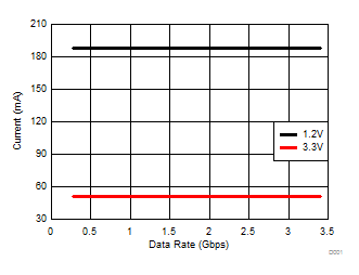
6.13 Typical Characteristics
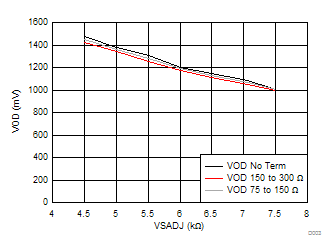
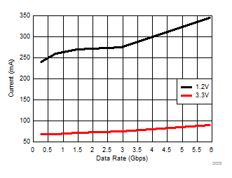
7 Parameter Measurement Information
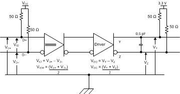 Figure 6. TMDS Main Link Test Circuit
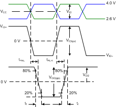 Figure 7. Input/Output Timing Measurements
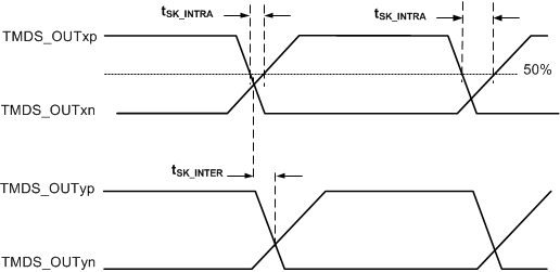 Figure 8. TMDS Output Skew Measurements
 Figure 9. HDMI/DVI TMDS Output Common Mode Measurement
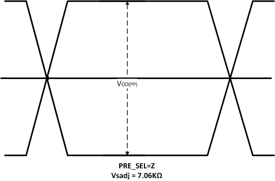 Figure 10. Output Differential Waveform
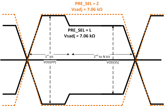 Figure 11. Output De-Emphasis Waveform
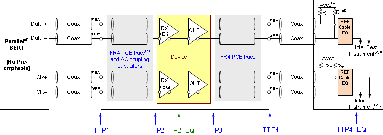
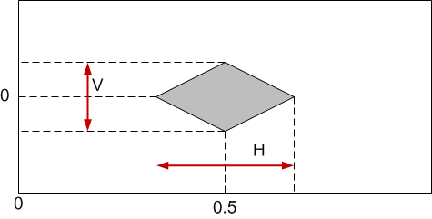
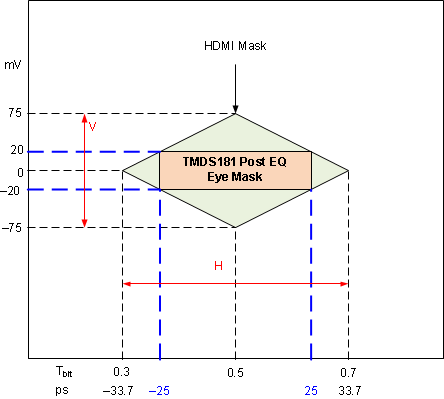 Figure 13. Input Eye Mask Post EQ – TTP2_EQ
Table 1. Output Eye Mask V and H Values
| TMDS Data Rate (Gbps) | H (Tbit) | V (mV) |
|---|---|---|
| 3.4 < DR < 3.712 | 0.6 | 335 |
| 3.712 < DR < 5.94 | –0.0332Rbit2 +0.2312 Rbit + 0.1998 | –19.66Rbit2 + 106.74Rbit + 209.58 |
| 5.94 ≤ DR ≤ 6.0 | 0.4 | 150 |
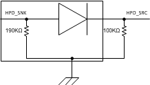 Figure 15. HPD Test Circuit
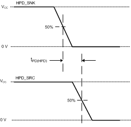 Figure 16. HPD Timing Diagram 1
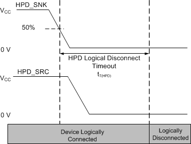 Figure 17. HPD Logic Disconnect Timeout
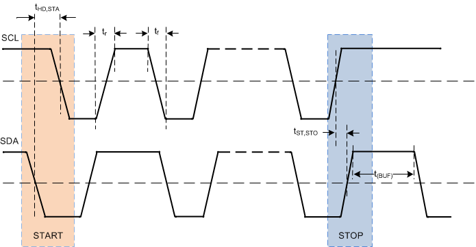 Figure 18. START and STOP Condition Timing
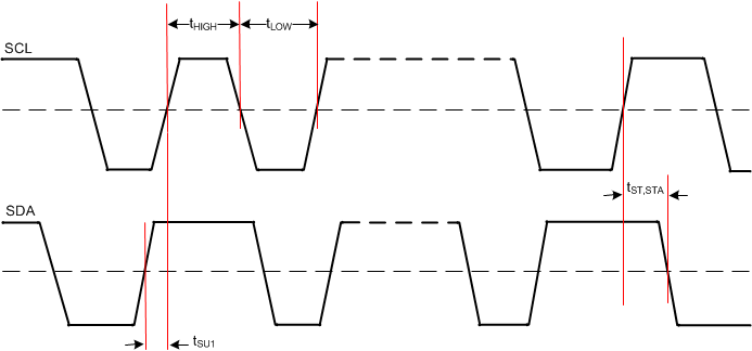 Figure 19. SCL and SDA Timing
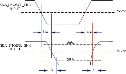 Figure 20. DDC Propagation Delay – Source to Sink
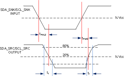 Figure 21. DDC Propagation Delay – Sink to Source
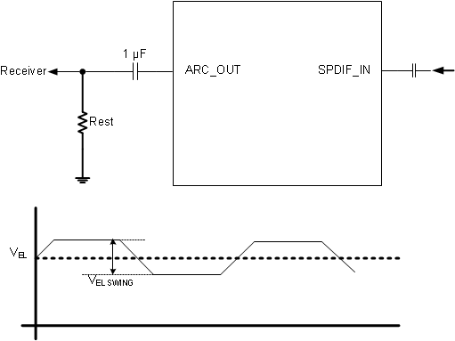 Figure 22. ARC Output
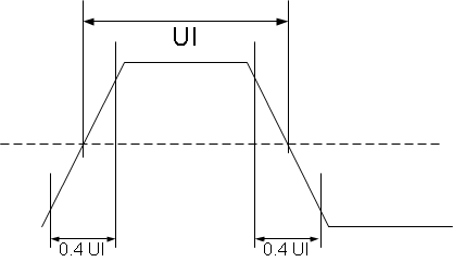 Figure 23. Rise and Fall Time of ARC

