JAJSI23I September 2009 – October 2019 TMP431 , TMP432
PRODUCTION DATA.
- 1 特長
- 2 アプリケーション
- 3 概要
- 4 改訂履歴
- 5 Pin Configuration and Functions
- 6 Specifications
- 7 Parameter Measurement Information
-
8 Detailed Description
- 8.1 Overview
- 8.2 Functional Block Diagram
- 8.3 Feature Description
- 8.4 Device Functional Modes
- 8.5 Programming
- 8.6
Register Maps
- 8.6.1 Pointer Register
- 8.6.2 Temperature Registers
- 8.6.3 Limit Registers
- 8.6.4 Status Registers
- 8.6.5 Configuration Register 1
- 8.6.6 Configuration Register 2
- 8.6.7 Conversion Rate Register
- 8.6.8 Beta Compensation Configuration Register
- 8.6.9 η-Factor Correction Register
- 8.6.10 Software Reset
- 8.6.11 Consecutive Alert Register
- 8.6.12 Therm Hysteresis Register
- 8.6.13 Identification Registers
- 8.6.14 Open Status Register
- 8.6.15 Channel Mask Register
- 8.6.16 High Limit Status Register
- 8.6.17 Low Limit Status Register
- 8.6.18 THERM Limit Status Register
- 9 Application and Implementation
- 10Power Supply Recommendations
- 11Layout
- 12デバイスおよびドキュメントのサポート
- 13メカニカル、パッケージ、および注文情報
8.6.7 Conversion Rate Register
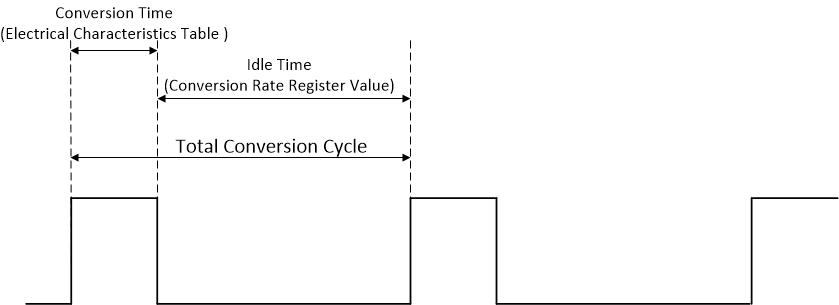
The Conversion Rate Register (pointer address 0Ah) controls the rate at which temperature conversions are performed. This register adjusts the idle time between conversions but not the conversion timing itself, thereby allowing the TMP43x power dissipation to be balanced with the temperature register update rate. Table 9 shows the conversion rate options and corresponding current consumption.
Table 9. Conversion Rate Register
| CONVERSION RATE REGISTER (Read = 04h, Write = 0Ah, POR = 07h) | ||||||||||
|---|---|---|---|---|---|---|---|---|---|---|
| R7 | R6 | R5 | R4 | R3 | R2 | R1 | R0 | CONVERSION PER SEC | AVERAGE IQ (TYP) (μA) | |
| V+ = 2.7 V | V+ = 5.5 V | |||||||||
| 0 | 0 | 0 | 0 | 0 | 0 | 0 | 0 | 0.0625 | 11 | 32 |
| 0 | 0 | 0 | 0 | 0 | 0 | 0 | 1 | 0.125 | 17 | 38 |
| 0 | 0 | 0 | 0 | 0 | 0 | 1 | 0 | 0.25 | 28 | 49 |
| 0 | 0 | 0 | 0 | 0 | 0 | 1 | 1 | 0.5 | 47 | 69 |
| 0 | 0 | 0 | 0 | 0 | 1 | 0 | 0 | 1 | 80 | 103 |
| 0 | 0 | 0 | 0 | 0 | 1 | 0 | 1 | 2 | 128 | 155 |
| 0 | 0 | 0 | 0 | 0 | 1 | 1 | 0 | 4 | 190 | 220 |
| 07h to 0Fh | 8 | 373 | 413 | |||||||
