JAJSC11D
October 2014 – December 2019
TPS1H100-Q1
PRODUCTION DATA.
1
特長
2
アプリケーション
3
概要
Device Images
代表的なアプリケーションの回路図
4
改訂履歴
5
Pin Configuration and Functions
Pin Functions
6
Specifications
6.1
Absolute Maximum Ratings
6.2
ESD Ratings
6.3
Recommended Operating Conditions
6.4
Thermal Information
6.5
Electrical Characteristics
6.6
Timing Requirements – Current Sense Characteristics
6.7
Switching Characteristics
6.8
Typical Characteristics
7
Detailed Description
7.1
Overview
7.2
Functional Block Diagram
7.3
Feature Description
7.3.1
Accurate Current Sense
7.3.2
Programmable Current Limit
7.3.3
Inductive-Load Switching-Off Clamp
7.3.4
Full Protections and Diagnostics
7.3.4.1
Short-to-GND and Overload Detection
7.3.4.2
Open-Load Detection
7.3.4.3
Short-to-Battery Detection
7.3.4.4
Reverse-Polarity Detection
7.3.4.5
Thermal Protection Behavior
7.3.4.6
UVLO Protection
7.3.4.7
Loss of GND Protection
7.3.4.8
Loss of Power Supply Protection
7.3.4.9
Reverse Current Protection
7.3.4.10
Protection for MCU I/Os
7.3.5
Diagnostic Enable Function
7.4
Device Functional Modes
7.4.1
Working Mode
8
Application and Implementation
8.1
Application Information
8.2
Typical Application
8.2.1
Design Requirements
8.2.2
Detailed Design Procedure
8.2.2.1
Distinguishing of Different Fault Modes
8.2.2.2
AEC Q100-012 Test Grade A Certification
8.2.2.3
EMC Transient Disturbances Test
8.2.3
Application Curves
9
Power Supply Recommendations
10
Layout
10.1
Layout Guidelines
10.2
Layout Example
10.2.1
Without a GND Network
10.2.2
With a GND Network
10.3
Thermal Considerations
11
デバイスおよびドキュメントのサポート
11.1
ドキュメントの更新通知を受け取る方法
11.2
コミュニティ・リソース
11.3
商標
11.4
静電気放電に関する注意事項
11.5
Glossary
12
メカニカル、パッケージ、および注文情報
パッケージ・オプション
メカニカル・データ(パッケージ|ピン)
PWP|14
MPDS370A
サーマルパッド・メカニカル・データ
発注情報
jajsc11d_oa
jajsc11d_pm
6.8
Typical Characteristics
All the following data are based on the mean value of the three lots samples, V
VS
= 13.5 V if not specified.
Figure 8.
V
VS,UVR
and V
VS,UVF
Figure 10.
I
off
and I
leak,out
Figure 12.
V
logic,h
and V
logic,l
Figure 14.
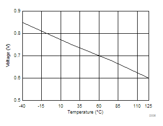
V
DS, clamp
Figure 16.
I
lim,nom
Figure 18.
dV/dtON and dV/dtOFF
Figure 20.
V
ol,off
Figure 22.
K
CS
= 5 mA, 13.5 V
Figure 24.
K
CS
= 50 mA, 13.5 V
Figure 26.
K
CS
= 1 A, 13.5 V
Figure 28.
K
CL
= 1.6 A, 13.5 V
Figure 9.
I
nom
With No Load and 10-Ω Load
Figure 11.
I
off,diag
Figure 13.
VF
Figure 15.
R
DSON
Figure 17.
TDon and TDoff
Figure 19.
V
CS,h
Figure 21.
I
ol,on
Figure 23.
K
CS
= 25 mA, 13.5 V
Figure 25.
K
CS
= 100 mA, 13.5 V
Figure 27.
K
CL
= 0.5 A, 13.5 V