JAJSJE1A July 2021 – December 2021 TPS1HC100-Q1
PRODUCTION DATA
- 1 特長
- 2 アプリケーション
- 3 説明
- 4 Revision History
- 5 Pin Configuration and Functions
- 6 Specifications
- 7 Parameter Measurement Information
-
8 Detailed Description
- 8.1 Overview
- 8.2 Functional Block Diagram
- 8.3
Feature Description
- 8.3.1 Accurate Current Sense
- 8.3.2 Programmable Current Limit
- 8.3.3 Inductive-Load Switching-Off Clamp
- 8.3.4
Full Protections and Diagnostics
- 8.3.4.1 Short-Circuit and Overload Protection
- 8.3.4.2 Open-Load and Short-to-Battery Detection
- 8.3.4.3 Short-to-Battery Detection
- 8.3.4.4 Reverse-Polarity and Battery Protection
- 8.3.4.5 Latch-Off Mode
- 8.3.4.6 Thermal Protection Behavior
- 8.3.4.7 UVLO Protection
- 8.3.4.8 Loss of GND Protection
- 8.3.4.9 Loss of Power Supply Protection
- 8.3.4.10 Reverse Current Protection
- 8.3.4.11 Protection for MCU I/Os
- 8.3.5 Diagnostic Enable Function
- 8.4 Device Functional Modes
- 9 Application and Implementation
- 10Power Supply Recommendations
- 11Layout
- 12Device and Documentation Support
- 13Mechanical, Packaging, and Orderable Information
パッケージ・オプション
デバイスごとのパッケージ図は、PDF版データシートをご参照ください。
メカニカル・データ(パッケージ|ピン)
- PWP|14
サーマルパッド・メカニカル・データ
発注情報
3 説明
TPS1HC100-Q1 デバイスは、各種の保護機能を搭載したハイサイド・パワー・スイッチで、NMOS パワー FET とチャージ・ポンプを内蔵して、各種負荷をインテリジェントに制御することを目標にしています。高精度の電流センスとプログラマブル電流制限機能により、市場での差別化に役立ちます。
入力ピンのロジック HIGH スレッショルド (VIH) が 1.5V と低いため、1.8V の MCU GPIO 信号 を使用できます。電流検出精度が高いため、追加キャリブレーションなしでも、より効果的なリアルタイム監視とより正確な診断が可能です。外付け抵抗による高精度電流制限機能を備えているので、アプリケーションに応じた電流制限値を設定できます。本デバイスは、スタートアップまたは短絡状態時に突入電流を効果的にクランプすることで、システムの信頼性を大きく向上させます。TPS1HC100-Q1 デバイスは、ワット数の低い電球、LED、リレー、ソレノイド、ヒーターなど、幅広い種類の抵抗性、誘導性、容量性負荷のためのハイサイド・パワー・スイッチとして使用できます。
製品情報(1)
| 部品番号 | パッケージ | 本体サイズ (公称) |
|---|---|---|
| TPS1HC100-Q1 | HTSSOP (14) | 4.40mm × 5.00mm |
(1) 利用可能なすべてのパッケージについては、このデータシートの末尾にある注文情報を参照してください。
機能ブロック図
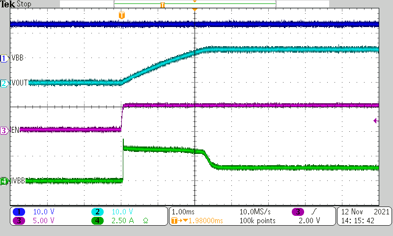
 容量性充電アプリケーション