SLVSB99C March 2012 – July 2015 TPS2378
PRODUCTION DATA.
- 1 Features
- 2 Applications
- 3 Description
- 4 Revision History
- 5 Pin Configuration and Functions
- 6 Specifications
-
7 Detailed Description
- 7.1 Overview
- 7.2 Functional Block Diagram
- 7.3 Feature Description
- 7.4
Device Functional Modes
- 7.4.1 PoE Overview
- 7.4.2 Threshold Voltages
- 7.4.3 PoE Start-up Sequence
- 7.4.4 Detection
- 7.4.5 Hardware Classification
- 7.4.6 Inrush and Start-up
- 7.4.7 Maintain Power Signature
- 7.4.8 Start-up and Converter Operation
- 7.4.9 PD Hotswap Operation
- 7.4.10 Start-up and Power Management, CDB and T2P
- 7.4.11 Adapter ORing
- 7.4.12 Using DEN to Disable PoE
- 7.4.13 ORing Challenges
- 8 Application and Implementation
- 9 Power Supply Recommendations
- 10Layout
- 11Device and Documentation Support
- 12Mechanical, Packaging, and Orderable Information
パッケージ・オプション
メカニカル・データ(パッケージ|ピン)
- DDA|8
サーマルパッド・メカニカル・データ
- DDA|8
発注情報
1 Features
2 Applications
- IEEE 802.3at-compliant Devices
- Video and VoIP Telephones
- Multiband Access Points
- Security Cameras
- Pico-base Stations
- Forced, Four-Pair, High Power Devices (SLVA625)
3 Description
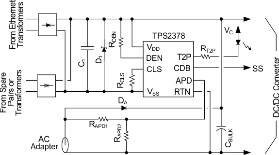
This 8-pin integrated circuit contains all of the features needed to implement an IEEE802.3at type-2 powered device (PD). The low 0.5-Ω internal switch resistance, combined with the enhanced thermal dissipation of the PowerPAD™ package, enables this controller to continuously handle up to 0.85 A. The TPS2378 features an auxiliary power detect (APD) input, providing priority for an external power adapter. It also features a 100-V pass transistor, 140-mA inrush current limiting, type-2 indication, auto-retry fault protection, and an open-drain power-good output.
Device Information(1)
| PART NUMBER | PACKAGE | BODY SIZE (NOM) |
|---|---|---|
| TPS2378 | HSOP (8) | 4.89 mm × 3.90 mm |
- For all available packages, see the orderable addendum at the end of the data sheet.
Typical Application Circuit
