JAJSK66A March   2021  – March 2022 TPS2521

PRODUCTION DATA  

  1. 特長
  2. アプリケーション
  3. 概要
  4. Revision History
  5. Device Comparison Table
  6. Pin Configuration and Functions
  7. Specifications
    1. 7.1 Absolute Maximum Ratings
    2. 7.2 ESD Ratings
    3. 7.3 Recommended Operating Conditions
    4. 7.4 Thermal Information
    5. 7.5 Electrical Characteristics
    6. 7.6 Timing Requirements
    7. 7.7 Switching Characteristics
      1.      15
    8. 7.8 Typical Characteristics
  8. Detailed Description
    1. 8.1 Overview
    2. 8.2 Functional Block Diagram
    3. 8.3 Feature Description
      1. 8.3.1 Input Reverse Polarity Protection
      2. 8.3.2 Undervoltage Lockout (UVLO and UVP)
      3. 8.3.3 Overvoltage Clamp (OVC)
      4. 8.3.4 Inrush Current, Overcurrent, and Short Circuit Protection
        1. 8.3.4.1 Slew Rate (dVdt) and Inrush Current Control
        2. 8.3.4.2 Active Current Limiting
        3. 8.3.4.3 Short-Circuit Protection
      5. 8.3.5 Analog Load Current Monitor
      6. 8.3.6 Reverse Current Protection
      7. 8.3.7 Overtemperature Protection (OTP)
      8. 8.3.8 Fault Response
      9. 8.3.9 Power Good Indication (PG)
    4. 8.4 Device Functional Modes
  9. Application and Implementation
    1. 9.1 Application Information
    2. 9.2 Single Device, Self-Controlled
    3. 9.3 Typical Application
      1. 9.3.1 Application
      2. 9.3.2 Design Requirements
      3. 9.3.3 Detailed Design Procedure
        1. 9.3.3.1 Device Selection
        2. 9.3.3.2 Setting Undervoltage and Overvoltage Thresholds
        3. 9.3.3.3 Setting Output Voltage Rise Time (tR)
        4. 9.3.3.4 Setting Power Good Assertion Threshold
        5. 9.3.3.5 Setting Overcurrent Threshold (ILIM)
        6. 9.3.3.6 Setting Overcurrent Blanking Interval (tITIMER)
      4. 9.3.4 Application Curves
  10. 10Power Supply Recommendations
    1. 10.1 Transient Protection
    2. 10.2 Output Short-Circuit Measurements
  11. 11Layout
    1. 11.1 Layout Guidelines
    2. 11.2 Layout Example
  12. 12Device and Documentation Support
    1. 12.1 Documentation Support
      1. 12.1.1 Related Documentation
    2. 12.2 Receiving Notification of Documentation Updates
    3. 12.3 サポート・リソース
    4. 12.4 Trademarks
    5. 12.5 Electrostatic Discharge Caution
    6. 12.6 Glossary
  13. 13Mechanical, Packaging, and Orderable Information

パッケージ・オプション

メカニカル・データ(パッケージ|ピン)
サーマルパッド・メカニカル・データ
発注情報

概要

TPS2521x ファミリの eFuse は、小さなパッケージに搭載され、高度に統合された回路保護および電源管理ソリューションです。このデバイスは、非常に少ない数の外付け部品で複数の保護モードを提供し、過負荷、短絡、電圧サージ、逆極性、過剰な突入電流に対して堅牢な保護を行います。内蔵バック・ツー・バック FET によって出力から入力への逆電流が常に阻止されるため、入力電源障害に備えた負荷側エネルギー保持ストレージを必要とするシステムに最適です。

出力電流制限レベルは、1 つの外付け抵抗により設定できます。また、電流制限抵抗の両端で電圧降下を測定することにより、出力負荷電流を正確に検出可能です。

特定の突入電流要件を持つアプリケーションでは、1 つの外付けコンデンサにより出力スルーレートを設定できます。出力を安全な固定最大電圧 (ピンで選択可能) にクランプすることで、入力過電圧状態から負荷を保護できます。

これらのデバイスは、2mm × 2mm、10 ピンの HotRod QFN パッケージで供給され、放熱性能の向上とシステムのフットプリントの削減に役立ちます。

これらのデバイスは、–40℃~+125℃の接合部温度範囲で動作が規定されています。

製品情報
部品番号パッケージ(1)本体サイズ (公称)
TPS2521xxRPWQFN (10)2mm × 2mm
利用可能なパッケージについては、このデータシートの末尾にある注文情報を参照してください。
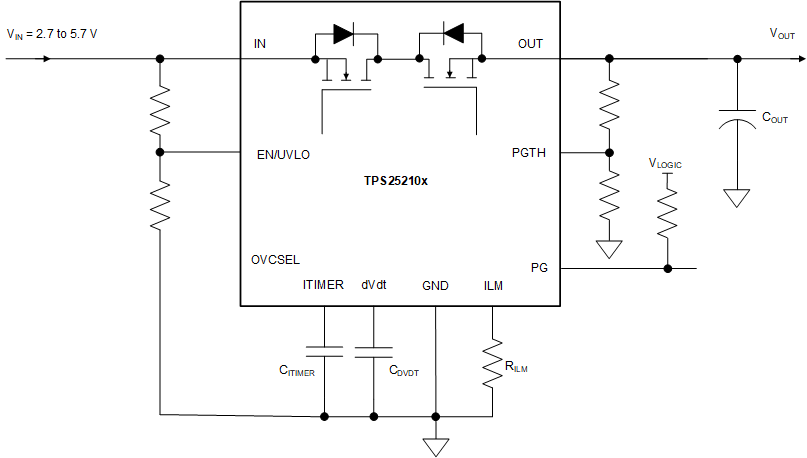
GUID-20210324-CA0I-PPPW-RLJB-GTXSLVP93XFF-low.gif概略回路図