SLVSH18 December   2024 TPS4HC120-Q1

PRODUCTION DATA  

  1.   1
  2. Features
  3. Applications
  4. Description
  5. Pin Configuration and Functions
    1.     6
  6. Specifications
    1. 5.1 Absolute Maximum Ratings
    2. 5.2 ESD Ratings
    3. 5.3 Recommended Operating Conditions
    4. 5.4 Thermal Information
    5. 5.5 Electrical Characteristics
    6. 5.6 SNS Timing Characteristics
    7. 5.7 Switching Characteristics
    8. 5.8 Typical Characteristics
  7. Detailed Description
    1. 6.1 Overview
    2. 6.2 Functional Block Diagram
    3. 6.3 Feature Description
      1. 6.3.1 Pin Current and Voltage Conventions
      2. 6.3.2 Low Power Mode
      3. 6.3.3 Accurate Current Sense
      4. 6.3.4 Adjustable Current Limit
      5. 6.3.5 Inductive-Load Switching-Off Clamp
      6. 6.3.6 Fault Detection and Reporting
        1. 6.3.6.1 Diagnostic Enable Function
        2. 6.3.6.2 Multiplexing of Current Sense
        3. 6.3.6.3 FAULT Reporting
        4. 6.3.6.4 Fault Table
      7. 6.3.7 Full Diagnostics
        1. 6.3.7.1 Short-to-GND and Overload Detection
        2. 6.3.7.2 Open-Load Detection
          1. 6.3.7.2.1 Channel On
          2. 6.3.7.2.2 Channel Off
        3. 6.3.7.3 Short-to-Battery Detection
        4. 6.3.7.4 Reverse-Polarity and Battery Protection
        5. 6.3.7.5 Thermal Fault Detection
          1. 6.3.7.5.1 Thermal Protection Behavior
      8. 6.3.8 Full Protections
        1. 6.3.8.1 UVLO Protection
        2. 6.3.8.2 Loss of GND Protection
        3. 6.3.8.3 Loss of Power Supply Protection
        4. 6.3.8.4 Reverse Polarity Protection
        5. 6.3.8.5 Protection for MCU I/Os
    4. 6.4 Device Functional Modes
      1. 6.4.1 Working Mode
  8. Application and Implementation
    1. 7.1 Application Information
    2. 7.2 Typical Application
      1. 7.2.1 Design Requirements
      2. 7.2.2 Detailed Design Procedure
      3. 7.2.3 Application Curves
    3. 7.3 EMC Transient Disturbances Test
    4. 7.4 Power Supply Recommendations
    5. 7.5 Layout
      1. 7.5.1 Layout Guidelines
      2. 7.5.2 Layout Examples
        1. 7.5.2.1 Without a GND Network
        2. 7.5.2.2 With a GND Network
  9. Device and Documentation Support
    1. 8.1 Receiving Notification of Documentation Updates
    2. 8.2 Support Resources
    3. 8.3 Trademarks
    4. 8.4 Electrostatic Discharge Caution
    5. 8.5 Glossary
  10. Revision History
  11. 10Mechanical, Packaging, and Orderable Information

パッケージ・オプション

メカニカル・データ(パッケージ|ピン)
サーマルパッド・メカニカル・データ
発注情報

Typical Characteristics

TPS4HC120-Q1 ISNS
            vs IOUT Over Temperature
VBB = 13.5V
Figure 5-1 ISNS vs IOUT Over Temperature
TPS4HC120-Q1 ISLEEP vs VBB Over Temperature
ENx = 0V DIAG_EN = 0V
Figure 5-3 ISLEEP vs VBB Over Temperature
TPS4HC120-Q1 RON
            vs VBB Over Temperature
IOUT = 0.5A
Figure 5-5 RON vs VBB Over Temperature
TPS4HC120-Q1 IQ,LPM vs VBB Over Temperature When 2 Channels are
            Enabled
EN1, 2 = 5V EN3, 4 = 0V DIAG_EN = 0V
Figure 5-7 IQ,LPM vs VBB Over Temperature When 2 Channels are Enabled
TPS4HC120-Q1 ISB
            vs VBB Over Temperature
DIAG_EN = 5V EN1 = 5V EN2, 3, 4 = 0V
No load condition
Figure 5-9 ISB vs VBB Over Temperature
TPS4HC120-Q1 SRF
            vs Temperature Over VBB VoltageFigure 5-11 SRF vs Temperature Over VBB Voltage
TPS4HC120-Q1 SRR
            vs Temperature Over VBB VoltageFigure 5-13 SRR vs Temperature Over VBB Voltage
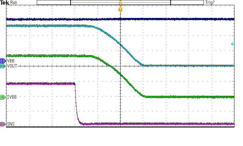
TPS4HC120-Q1 Switch
            Turn-Off
VBB = 13.5V RSNS = 1kΩ ILIM = OPEN
ROUT = 10Ω TAMB = 25°C
Figure 5-15 Switch Turn-Off
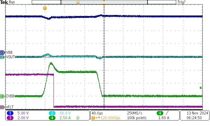
TPS4HC120-Q1 Permanent Short
            Behavior With ILIM Open
VBB = 13.5V RSNS = 1kΩ ILIM = OPEN
ZOUT = 100mΩ + 5μH TAMB = 25°C
Figure 5-17 Permanent Short Behavior With ILIM Open
TPS4HC120-Q1 ISNS
            vs IOUT Over VBB Voltage
TAMB = 25°C
Figure 5-2 ISNS vs IOUT Over VBB Voltage
TPS4HC120-Q1 RON
            vs IOUT Over Temperature
VBB = 13.5V
Figure 5-4 RON vs IOUT Over Temperature
TPS4HC120-Q1 IQ,LPM vs VBB Over Temperature When 1 Channel is
            Enabled
EN1 = 5V EN2, 3, 4 = 0V DIAG_EN = 0V
Figure 5-6 IQ,LPM vs VBB Over Temperature When 1 Channel is Enabled
TPS4HC120-Q1 IQ,LPM vs VBB Over Temperature When 4 Channels are
            Enabled
EN1, 2, 3, 4 = 5V DIAG_EN = 0V
Figure 5-8 IQ,LPM vs VBB Over Temperature When 4 Channels are Enabled
TPS4HC120-Q1 tDF
            vs Temperature Over VBB VoltageFigure 5-10 tDF vs Temperature Over VBB Voltage
TPS4HC120-Q1 tDR
            vs Temperature Over VBB VoltageFigure 5-12 tDR vs Temperature Over VBB Voltage
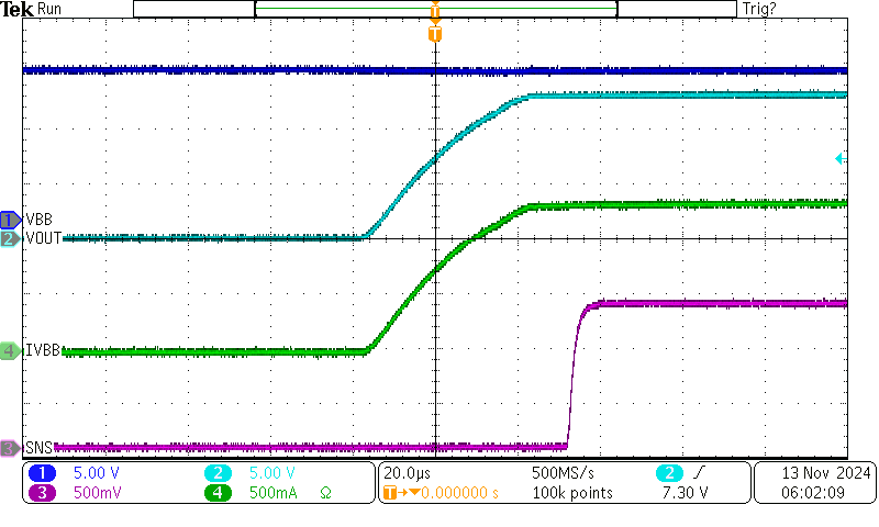
TPS4HC120-Q1 Switch
            Turn-On
VBB = 13.5V RSNS = 1kΩ ILIM = OPEN
ROUT = 10Ω TAMB = 25°C
Figure 5-14 Switch Turn-On
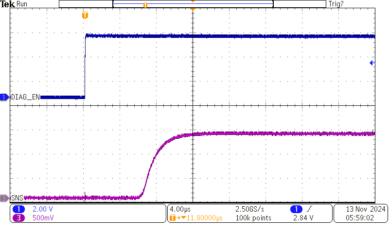
TPS4HC120-Q1 SNS Pin Voltage
            With DIAG_EN Turning ON
VBB = 13.5V RSNS = 1kΩ ILIM = OPEN
ROUT = 10Ω TAMB = 25°C
Figure 5-16 SNS Pin Voltage With DIAG_EN Turning ON
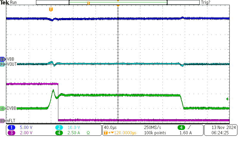
TPS4HC120-Q1 Permanent Short
            Behavior With ILIM Short-to-GND
VBB = 13.5V RSNS = 1kΩ ILIM = Short-to-GND
ZOUT = 100mΩ + 5μH TAMB = 25°C
Figure 5-18 Permanent Short Behavior With ILIM Short-to-GND