-
TPS54062 低IQ、4.7V~60V入力、50mA同期整流降圧型コンバータ
- 1 特長
- 2 アプリケーション
- 3 概要
- 4 改訂履歴
- 5 Pin Configuration and Functions
- 6 Specifications
-
7 Detailed Description
- 7.1 Overview
- 7.2 Functional Block Diagram
- 7.3
Feature Description
- 7.3.1 Fixed-Frequency PWM Control
- 7.3.2 Slope Compensation Output Current
- 7.3.3 Error Amplifier
- 7.3.4 Voltage Reference
- 7.3.5 Adjusting the Output Voltage
- 7.3.6 Enable and Adjusting Undervoltage Lockout
- 7.3.7 Constant Switching Frequency and Timing Resistor (RT/CLK Pin)
- 7.3.8 Selecting the Switching Frequency
- 7.3.9 How to Interface to RT/CLK Pin
- 7.3.10 Overvoltage Transient Protection
- 7.3.11 Thermal Shutdown
- 7.4 Device Functional Modes
-
8 Applications and Implementation
- 8.1 Application Information
- 8.2
Typical Applications
- 8.2.1
Continuous Conduction Mode (CCM) Switching Regulator
- 8.2.1.1 Design Requirements
- 8.2.1.2
Detailed Design Procedure
- 8.2.1.2.1 Selecting the Switching Frequency
- 8.2.1.2.2 Output Inductor Selection (LO)
- 8.2.1.2.3 Output Capacitor
- 8.2.1.2.4 Input capacitor
- 8.2.1.2.5 Bootstrap Capacitor Selection
- 8.2.1.2.6 Under Voltage Lock Out Set Point
- 8.2.1.2.7 Output Voltage and Feedback Resistors Selection
- 8.2.1.2.8 Closing the Loop
- 8.2.1.3 Application Curves
- 8.2.2 DCM Application
- 8.2.1
Continuous Conduction Mode (CCM) Switching Regulator
- 9 Power Supply Recommendations
- 10Layout
- 11デバイスおよびドキュメントのサポート
- 12メカニカル、パッケージ、および注文情報
- 重要なお知らせ
パッケージ・オプション
メカニカル・データ(パッケージ|ピン)
サーマルパッド・メカニカル・データ
- DRB|8
発注情報
DATA SHEET
TPS54062 低IQ、4.7V~60V入力、50mA同期整流降圧型コンバータ
このリソースの元の言語は英語です。 翻訳は概要を便宜的に提供するもので、自動化ツール (機械翻訳) を使用していることがあり、TI では翻訳の正確性および妥当性につきましては一切保証いたしません。 実際の設計などの前には、ti.com で必ず最新の英語版をご参照くださいますようお願いいたします。
1 特長
2 アプリケーション
- 低消費電力のスタンバイまたはバイアス電圧電源
- 4~20mAの電流ループ駆動センサ
- 工業用プロセス制御、計量、およびセキュリティ・システム
- 高電圧のリニア・レギュレータの代替
3 概要
TPS54062デバイスは60V、50mAの同期整流降圧型コンバータで、ハイサイドおよびローサイドのMOSFETが内蔵されています。電流モード制御により、外部補償が単純化され、柔軟な部品選択が可能になります。非スイッチング時の消費電流は89µAです。イネーブル・ピンにより、シャットダウン時の消費電流を1.7µAまで低減できます。
低電圧誤動作防止は内部で 4.5Vに設定されていますが、正確なイネーブル・ピンのスレッショルドを使用して、さらに高い電圧に設定できます。出力電圧のスタートアップ・ランプは、内部のスロースタート時間により制御されます。
スイッチング周波数の範囲を調整可能なため、効率と外付け部品のサイズを最適化できます。周波数のフォールドバックとサーマル・シャットダウンにより、過負荷状態時にデバイスが保護されます。
製品情報(1)
| 型番 | パッケージ | 本体サイズ(公称) |
|---|---|---|
| TPS54062 | MSOP (8) | 3.00mm×3.00mm |
| VSON (8) |
- 利用可能なすべてのパッケージについては、このデータシートの末尾にある注文情報を参照してください。
4 改訂履歴
Changes from C Revision (December 2014) to D Revision
- Added text to the Layout Guidelines section " All sensitive analog traces and components..."Go
Changes from B Revision (August 2012) to C Revision
- 「取り扱い定格」表、「機能説明」セクション、「デバイスの機能モード」セクション、「アプリケーションと実装」セクション、「電源に関する推奨事項」セクション、「レイアウト」セクション、「デバイスおよびドキュメントのサポート」セクション、「メカニカル、パッケージ、および注文情報」セクションを追加Go
Changes from A Revision (October 2011) to B Revision
- 特長の項目に「ダイオード・エミュレーションにより軽負荷時の効率を改善」を追加Go
- 特長の項目を「100kHz~400kHzのスイッチング周波数」から「スイッチング周波数を100kHz~400kHzに調整可能」に変更Go
- 効率のグラフを変更Go
- Changed VSON-8 package graphic to clarify ThermalPAD areaGo
- Changed the EN pin MAX value From: 5 V To: 8 VGo
- Changed the Enable and Adjusting Undervoltage Lockout sectionGo
- Changed Equation 22 through Equation 25Go
Changes from * Revision (May 2011) to A Revision
- 特長の項目を「MSOP8およびWSON8パッケージ」から「MSOP-8および3mm×3mm VSON-8パッケージ」へ変更Go
- 効率のグラフを変更Go
- Added the VSON (DRB-8 Pin) PackageGo
- Changed the RT/CLK pin DescriptionGo
- Added VSON-8 Pins values to the Thermal Information tableGo
- Changed the PLL lock in time Unit of Measure From: µA To: µsGo
- Changed Equation 22Go
- Changed the Efficiency vs Output Current Graphs, Figure 21 and Figure 22Go
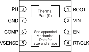
5 Pin Configuration and Functions
MSOP PACKAGE
8 PINS
TOP VIEW
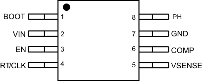
Pin Functions
| PIN | I/O | DESCRIPTION | |
|---|---|---|---|
| NAME | NUMBER | ||
| BOOT | 1 | O | A bootstrap capacitor is required between BOOT and PH. If the voltage on this capacitor is below the minimum required by the output device, the output is forced to switch off until the capacitor is refreshed. |
| VIN | 2 | I | Input supply voltage, 4.7 V to 60 V. |
| EN | 3 | I | Enable pin, internal pull-up current source. Pull below 1.14 V to disable. Float to enable. Adjust the input undervoltage lockout with two resistors, see the Enable and Adjusting Undervoltage Lockout section. |
| RT/CLK | 4 | I | Resistor Timing and External Clock. An internal amplifier holds this pin at a fixed voltage when using an external resistor to ground to set the switching frequency. If the pin is pulled above the PLL upper threshold, a mode change occurs and the pin becomes a synchronization input. The internal amplifier is disabled and the pin is a high impedance clock input to the internal PLL. If clocking edges stop, the internal amplifier is re-enabled and the mode returns to a resistor frequency programming. |
| VSENSE | 5 | I | Inverting input of the transconductance (gm) error amplifier. |
| COMP | 6 | O | Error amplifier output, and input to the output switch current comparator. Connect frequency compensation components to this pin. |
| GND | 7 | – | Ground |
| PH | 8 | O | The source of the internal high-side power MOSFET and drain of the internal low side MOSFET |
| Thermal Pad | 9 | – | GND pin must be electrically connected to the exposed pad on the printed circuit board for proper operation. VSON-8 package only. |
6 Specifications
6.1 Absolute Maximum Ratings(1)
over operating free-air temperature range (unless otherwise noted)(1) The Absolute Maximum Ratings specified in this section will apply to all specifications of this document unless otherwise noted. These specifications will be interpreted as the conditions which may damage the device with a single occurrence.
6.2 ESD Ratings
| VALUE | UNIT | |||
|---|---|---|---|---|
| V(ESD) | Electrostatic discharge | Human-body model (HBM), per ANSI/ESDA/JEDEC JS-001(1) | ±2000 | V |
| Charged-device model (CDM), per JEDEC specification JESD22-C101(2) | ±500 | |||
(1) JEDEC document JEP155 states that 500-V HBM allows safe manufacturing with a standard ESD control process.
(2) JEDEC document JEP157 states that 250-V CDM allows safe manufacturing with a standard ESD control process.
6.3 Recommended Operating Conditions
over operating free-air temperature range (unless otherwise noted)| MIN | MAX | UNIT | ||
|---|---|---|---|---|
| Input coltage | 4.7 | 60 | V | |
| Output current | 50 | mA | ||
| Switching frequency set by RT/CLK resistor | 100 | 400 | kHz | |
| Switching frequency synchronized to external clock | 300 | 400 | kHz | |
6.4 Thermal Information
| THERMAL METRIC(1) | TPS54062 | UNIT | ||
|---|---|---|---|---|
| MSOP | VSON | |||
| 8 PINS | 8 PINS | |||
| RθJA | Junction-to-ambient thermal resistance | 127.1 | 40.2 | °C/W |
| RθJC(top) | Junction-to-case (top) thermal resistance | 33.4 | 49.7 | |
| RθJB | Junction-to-board thermal resistance | 80 | 15.7 | |
| ψJT | Junction-to-top characterization parameter | 1 | 0.6 | |
| ψJB | Junction-to-board characterization parameter | 79 | 15.9 | |
| RθJC(bot) | Junction-to-case (bottom) thermal resistance | N/A | 4.1 | |
(1) For more information about traditional and new thermal metrics, see the Semiconductor and IC Package Thermal Metrics application report.
6.5 Electrical Characteristics(1)
TJ = –40°C to 125°C, VIN = 4.7 to 60 V (unless otherwise noted)(1) The Electrical Ratings specified in this section will apply to all specifications in this document unless otherwise noted. These specifications will be interpreted as conditions that will not degrade the device’s parametric or functional specifications for the life of the product containing it.
6.6 Typical Characteristics
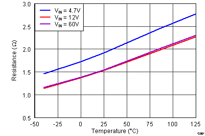 Figure 1. High-Side RDS(on) vs Temperature
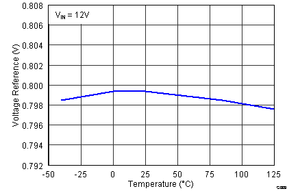 Figure 3. VREF Voltage vs Temperature
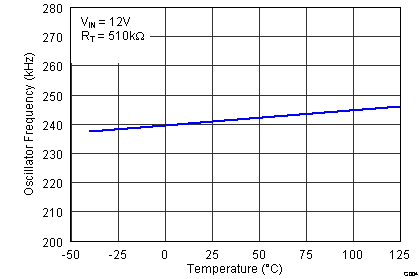 Figure 5. Frequency vs Temperature
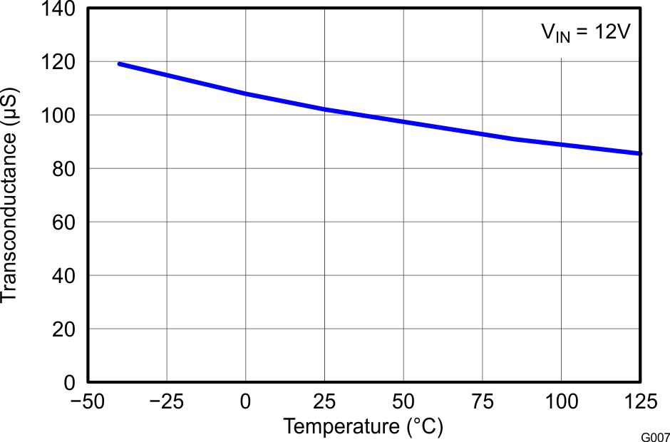 Figure 7. Error Amp Transconductance vs Temperature
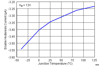 Figure 9. Enable Pin Hysteresis Current
vs Temperature
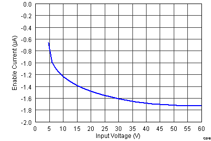 Figure 11. Enable Pin Pullup Current vs Input Voltage
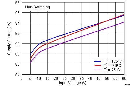 Figure 13. Supply Current (VIN pin) vs Input Voltage
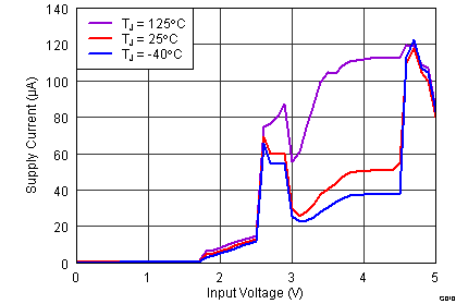 Figure 15. Supply Current (VIN pin) vs
Input Voltage (0V to VSTART) EN Pin Open
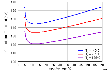 Figure 17. Current Limit vs
Input Voltage
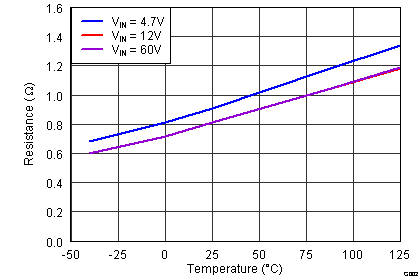 Figure 2. Low-Side RDS(on) vs Temperature
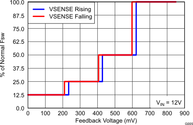 Figure 4. Frequency vs VSENSE Voltage
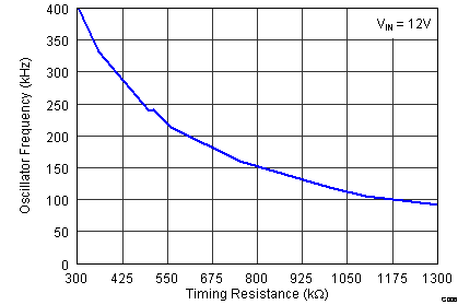 Figure 6. Frequency vs RT/CLK Resistance
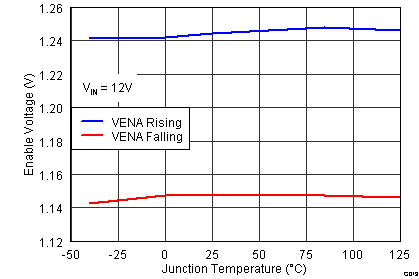 Figure 8. Enable Pin Voltage vs Temperature
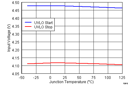 Figure 10. Input Voltage (UVLO) vs Temperature
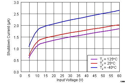 Figure 12. Shutdown Supply Current (VIN) vs Input Voltage
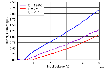 Figure 14. Supply Current (VIN pin)
 vs Input Voltage (0V to VSTART) EN Pin Low
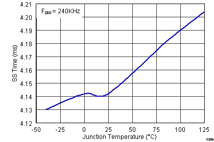 Figure 16. Slow-Start Time vs Temperature


