JAJS298D DECEMBER 2003 – June 2019 TPS54110
PRODUCTION DATA.
- 1 特長
- 2 アプリケーション
- 3 概要
- 4 改訂履歴
- 5 Device Information
- 6 Pin Configuration and Functions
- 7 Specifications
- 8 Detailed Description
- 9 Application and Implementation
- 10Layout
- 11デバイスおよびドキュメントのサポート
- 12メカニカル、パッケージ、および注文情報
パッケージ・オプション
デバイスごとのパッケージ図は、PDF版データシートをご参照ください。
メカニカル・データ(パッケージ|ピン)
- PWP|20
サーマルパッド・メカニカル・データ
- PWP|20
発注情報
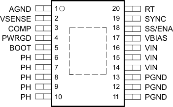
6 Pin Configuration and Functions
PWP Package
20-Pin HTSSOP With PowerPAD
Top View

Pin Functions
| PIN | DESCRIPTION | |
|---|---|---|
| NAME | NO. | |
| AGND | 1 | Analog ground—internally connected to the sensitive analog-ground circuitry. Connect to PGND and PowerPAD. |
| BOOT | 5 | Bootstrap input. 0.022-µF to 0.1-µF low-ESR capacitor connected from BOOT to PH generates floating drive for the high-side FET driver. |
| COMP | 3 | Error amplifier output. Connect compensation network from COMP to VSENSE. |
| PGND | 11–13 | Power ground. High current return for the low-side driver and power MOSFET. Connect PGND with large copper areas to the input and output supply returns, and negative terminals of the input and output capacitors. Connect to AGND and PowerPAD. |
| PH | 6–10 | Phase input/output. Junction of the internal high and low-side power MOSFETs, and output inductor. |
| PWRGD | 4 | Power-good open drain output. High when VSENSE ≥ 93% Vref, otherwise PWRGD is low. Note that output is low when SS/ENA is low or internal shutdown signal active. |
| RT | 20 | Frequency setting resistor input. Connect a resistor from RT to AGND to set the switching frequency, fs. |
| SS/ENA | 18 | Slow-start/enable input/output. Dual-function pin that provides logic input to enable/disable device operation and capacitor input to externally set the start-up time. |
| SYNC | 19 | Synchronization input. Dual-function pin that provides logic input to synchronize to an external oscillator or pin select between two internally set switching frequencies. When used to synchronize to an external signal, a resistor must be connected to the RT pin. |
| VBIAS | 17 | Internal bias regulator output. Supplies regulated voltage to internal circuitry. Bypass VBIAS pin to AGND pin with a high quality, low ESR 0.1-µF to 1-µF ceramic capacitor. |
| VIN | 14–16 | Input supply for the power MOSFET switches and internal bias regulator. Bypass VIN pins to PGND pins close to device package with a high quality, low ESR 1-µF to 10-µF ceramic capacitor. |
| VSENSE | 2 | Error amplifier inverting input. |