JAJSK12C September 2020 – December 2021 TPS542A50
PRODUCTION DATA
- 1 特長
- 2 アプリケーション
- 3 概要
- 4 Revision History
- 5 Pin Configuration and Functions
- 6 Specifications
-
7 Detailed Description
- 7.1 Overview
- 7.2 Functional Block Diagram
- 7.3
Feature Description
- 7.3.1 Enable and Adjustable Undervoltage Lockout
- 7.3.2 Input and VREG Undervoltage Lockout Protection
- 7.3.3 Voltage Reference and Setting the Output Voltage
- 7.3.4 Remote Sense Function
- 7.3.5 Switching Frequency
- 7.3.6 Voltage Control Mode Internal Compensation
- 7.3.7 Soft Start and Prebiased Output Start-up
- 7.3.8 Power Good
- 7.3.9 Overvoltage and Undervoltage Protection
- 7.3.10 Overcurrent Protection
- 7.3.11 High-Side FET Throttling
- 7.3.12 Overtemperature Protection
- 7.4 Device Functional Modes
- 7.5 Programming
- 7.6 Pin-Strap Programming
- 7.7
Register Maps
- 7.7.1 ID Register (Offset = 0x0) [reset = 0x21]
- 7.7.2 STATUS Register (Offset = 0x1) [reset = 0x0]
- 7.7.3 VOUT_ADJ1 Register (Offset = 0x2) [reset = 0x0]
- 7.7.4 VOUT_ADJ2 Register (Offset = 0x3) [reset = 0x0]
- 7.7.5 CONFIG1 Register (Offset = 0x4) [reset = 0x0B]
- 7.7.6 CONFIG2 Register (Offset = 0x5) [reset = 0x2D]
-
8 Application and Implementation
- 8.1 Application Information
- 8.2
Typical Application
- 8.2.1
Full Analog Configuration
- 8.2.1.1 Design Requirements
- 8.2.1.2
Detailed Design Procedure
- 8.2.1.2.1 Custom Design With WEBENCH® Tools
- 8.2.1.2.2 Output Voltage Calculation
- 8.2.1.2.3 Switching Frequency Selection
- 8.2.1.2.4 Inductor Selection
- 8.2.1.2.5 Input Capacitor Selection
- 8.2.1.2.6 Bootstrap Capacitor Selection
- 8.2.1.2.7 R-C Snubber and VIN Pin High-Frequency Bypass
- 8.2.1.2.8 Output Capacitor Selection
- 8.2.1.2.9 Response to a Load Transient
- 8.2.1.2.10 Pin-Strap Setting
- 8.2.1.3 Application Curves
- 8.2.1.4 Typical Application Circuits
- 8.2.1
Full Analog Configuration
- 9 Power Supply Recommendations
- 10Layout
- 11Device and Documentation Support
- 12Mechanical, Packaging, and Orderable Information
3 概要
TPS542A50 は、差動リモート・センス機能と I2C を備えた高効率の同期整流式降圧コンバータですこのデバイスは、システム・コストと複雑さを低減するためピンストラップで選択可能な内部補償機能を備えた固定周波数電圧制御モードを特長としています。PWM は、SYNC ピンを介して外部クロックに同期させることができます。その他の主な特長として、PFM による軽負荷時の効率向上、小さいシャットダウン時静止電流、EN ピンで調整可能な UVLO、プリバイアス条件での単調な起動などがあります。このデバイスは、デバイス構成と出力電圧調整のための I2C インターフェイスも備えています。TPS542A50 は鉛フリー・デバイスです。RoHS に完全準拠しています (適用除外なし)。
製品情報
| 型番 | パッケージ(1) | 本体サイズ (公称) |
|---|---|---|
| TPS542A50 | VQFN (33) | 4.50mm × 4.00mm |
(1) 利用可能なすべてのパッケージについては、このデータシートの末尾にある注文情報を参照してください。
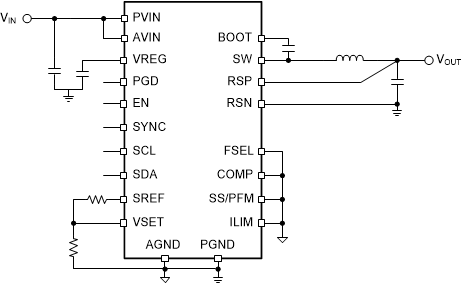
 概略回路図
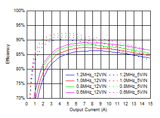
概略回路図 代表的な効率 (VOUT = 1V の場合)