-
TPS54824 4.5V~17V入力、電流モード、8A同期整流降圧型SWIFT™コンバータ
- 1 特長
- 2 アプリケーション
- 3 概要
- 4 改訂履歴
- 5 Pin Configuration and Functions
- 6 Specifications
-
7 Detailed Description
- 7.1 Overview
- 7.2 Functional Block Diagram
- 7.3
Feature Description
- 7.3.1 Fixed Frequency PWM Control
- 7.3.2 Continuous Conduction Mode Operation (CCM)
- 7.3.3 VIN Pins and VIN UVLO
- 7.3.4 Voltage Reference and Adjusting the Output Voltage
- 7.3.5 Error Amplifier
- 7.3.6 Enable and Adjustable UVLO
- 7.3.7 Soft Start and Tracking
- 7.3.8 Safe Start-up into Pre-Biased Outputs
- 7.3.9 Power Good
- 7.3.10 Sequencing (SS/TRK)
- 7.3.11 Adjustable Switching Frequency (RT Mode)
- 7.3.12 Synchronization (CLK Mode)
- 7.3.13 Bootstrap Voltage and 100% Duty Cycle Operation (BOOT)
- 7.3.14 Output Overvoltage Protection (OVP)
- 7.3.15 Overcurrent Protection
- 7.4 Device Functional Modes
-
8 Application and Implementation
- 8.1 Application Information
- 8.2
Typical Application
- 8.2.1 Design Requirements
- 8.2.2
Detailed Design Procedure
- 8.2.2.1 Switching Frequency
- 8.2.2.2 Output Inductor Selection
- 8.2.2.3 Output Capacitor
- 8.2.2.4 Input Capacitor
- 8.2.2.5 Output Voltage Resistors Selection
- 8.2.2.6 Soft-start Capacitor Selection
- 8.2.2.7 Undervoltage Lockout Set Point
- 8.2.2.8 Bootstrap Capacitor Selection
- 8.2.2.9 PGOOD Pull-up Resistor
- 8.2.2.10 Compensation
- 8.2.3 Application Curves
- 9 Power Supply Recommendations
- 10Layout
- 11デバイスおよびドキュメントのサポート
- 12メカニカル、パッケージ、および注文情報
- 重要なお知らせ
DATA SHEET
TPS54824 4.5V~17V入力、電流モード、8A同期整流降圧型SWIFT™コンバータ
このリソースの元の言語は英語です。 翻訳は概要を便宜的に提供するもので、自動化ツール (機械翻訳) を使用していることがあり、TI では翻訳の正確性および妥当性につきましては一切保証いたしません。 実際の設計などの前には、ti.com で必ず最新の英語版をご参照くださいますようお願いいたします。
1 特長
- 小型3.5mm×3.5mm HotRod™QFNパッケージ
- 14.1mΩおよび6.1mΩのMOSFETを内蔵
- 過渡応答が高速なピーク電流モード制御
- 200kHz~1.6MHzの固定スイッチング周波数
- 外部クロックに同期
- 温度範囲全体にわたって0.6V±0.85%の基準電圧
- 0.6V~12Vの出力電圧範囲
- ヒカップ電流制限
- プリバイアス出力電圧への安全なスタートアップ
- 調整可能なソフトスタートおよび電源シーケンシング
- 調整可能な入力低電圧誤動作防止
- シャットダウン時電流: 3µA
- 低電圧および過電圧用のパワーグッド出力モニタ
- 出力過電圧保護
- 非ラッチ型サーマル・シャットダウン保護機能
- 動作時接合部温度: -40℃~150℃
- WEBENCH® Design Centerでサポート
2 アプリケーション
- 電気通信および無線インフラストラクチャ
- 産業用自動化試験装置
- エンタープライズ向けスイッチング/ストレージ・アプリケーション
- 高密度分散電源システム
3 概要
TPS54824は完全な機能を持つ17V、8Aの同期整流降圧型コンバータで、3.5mm×3.5mmの HotRod™ QFNパッケージで供給されます。
小型化を追求するため、効率を高めるとともに、ハイサイドMOSFETとローサイドMOSFETを統合しました。ピーク電流モード制御による部品数の削減と、高いスイッチング周波数によるインダクタの占有面積削減により、さらに容積が節約されています。
ピーク電流モード制御によりループ補償が簡素化され、過渡応答が高速です。過負荷状態の保護のため、ハイサイドおよびローサイドのソース電流に、サイクルごとのピーク電流制限が使用されます。ヒカップ機能は、短絡または過負荷障害が発生した場合に、MOSFETの電力損失を制限します。
パワーグッド・スーパーバイザ回路は、レギュレータの出力をモニタします。PGOODピンは、オープン・ドレイン出力で、出力電圧が安定化されているときハイ・インピーダンスになります。内部デグリッチ時間があるため、PGOODピンは障害が発生しない限り"L"になりません。
専用のENピンを使用して、レギュレータをオン/オフし、入力低電圧誤動作防止を調整できます。出力電圧のスタートアップ・ランプはSS/TRKピンにより制御されるため、スタンドアロンの電源として、あるいはトラッキング状況でも動作できます。
製品情報(1)
| 型番 | パッケージ | 本体サイズ(公称) |
|---|---|---|
| TPS54824 | RNV (18) | 3.50mm×3.50mm |
- 提供されているすべてのパッケージについては、巻末の注文情報を参照してください。
概略回路図

効率

4 改訂履歴
Changes from * Revision (November 2016) to A Revision
- Changed the VIN MAX value From: 18 V To: 19 V in the Absolute Maximum RatingsGo
- Changed the BOOT MAX value From: 25 V To: 27 V in the Absolute Maximum RatingsGo
- Changed the BOOT (10 ns transient) MAX value From: 27 V To: 30 V in the Absolute Maximum RatingsGo
- Changed the BOOT (vs SW) MAX value From: 6.5 V To: 7 V in the Absolute Maximum RatingsGo
- Changed the SW MAX value From: 19 V To: 20 V in the Absolute Maximum RatingsGo
- Changed the SW (10 ns transient) MAX value From: 21 V To: 23 V in the Absolute Maximum RatingsGo
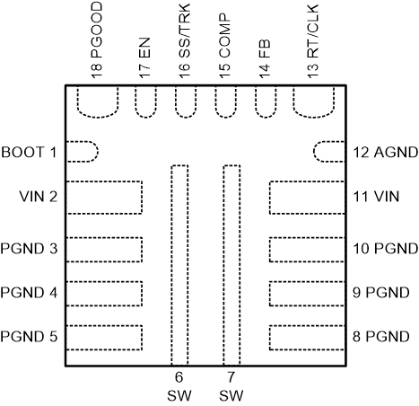
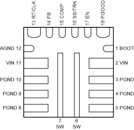
5 Pin Configuration and Functions
RNV Package
18-Pin VQFN-HR
Top View

Bottom View

Pin Functions
| PIN | I/O | DESCRIPTION | |
|---|---|---|---|
| NAME | NO. | ||
| BOOT | 1 | I | Floating supply voltage for high-side MOSFET gate drive circuit. Connect a 0.1-µF ceramic capacitor between BOOT and SW pins. |
| VIN | 2, 11 | I | Input voltage supply pin. Power for the internal circuit and the connection to drain of high-side MOSFET. Connect both pins to the input power source with a low impedance connection. Connect both pins and their neighboring PGND pins. |
| PGND | 3, 4, 5, 8, 9, 10 | – | Ground return for low-side power MOSFET and its drivers. |
| SW | 6, 7 | O | Switching node. Connected to the source of the high-side MOSFET and drain of the low-side MOSFET. |
| AGND | 12 | – | Ground of internal analog circuitry. AGND must be connected to the PGND plane. |
| RT/CLK | 13 | I | Switching frequency setting pin. In RT mode, an external timing resistor adjusts the switching frequency. In CLK mode, the device synchronizes to an external clock input to this pin. |
| FB | 14 | I | Converter feedback input. Connect to the output voltage with a resistor divider. |
| COMP | 15 | I | Error amplifier output and input to the PWM modulator. Connect loop compensation to this pin. |
| SS/TRK | 16 | I | Soft-start and tracking pin. Connecting an external capacitor sets the soft-start time. This pin can also be used for tracking and sequencing. |
| EN | 17 | I | Enable pin. Float or pull high to enable the device. Connect a resistor divider to this pin to implement adjustable under voltage lockout and hysteresis. |
| PGOOD | 18 | O | Open-drain power good indicator. It is asserted low if output voltage is outside if the PGOOD thresholds, VIN is low, EN is low, device is in thermal shutdown or device is in soft-start. |