JAJSDE0A June   2017  – February 2024 TPS549B22

PRODUCTION DATA  

  1.   1
  2. 特長
  3. アプリケーション
  4. 概要
  5. Pin Configuration and Functions
  6. Specifications
    1. 5.1 Absolute Maximum Ratings
    2. 5.2 ESD Ratings
    3. 5.3 Recommended Operating Conditions
    4. 5.4 Thermal Information
    5. 5.5 Electrical Characteristics
    6. 5.6 Typical Characteristics
  7. Detailed Description
    1. 6.1 Overview
    2. 6.2 Functional Block Diagram
    3. 6.3 Feature Description
      1. 6.3.1 25-A FET
      2. 6.3.2 On-Resistance
      3. 6.3.3 Package Size, Efficiency and Thermal Performance
      4. 6.3.4 Soft-Start Operation
      5. 6.3.5 VDD Supply Undervoltage Lockout (UVLO) Protection
      6. 6.3.6 EN_UVLO Pin Functionality
      7. 6.3.7 Fault Protections
        1. 6.3.7.1 Current Limit (ILIM) Functionality
        2. 6.3.7.2 VDD Undervoltage Lockout (UVLO)
        3. 6.3.7.3 Overvoltage Protection (OVP) and Undervoltage Protection (UVP)
        4. 6.3.7.4 Out-of-Bounds Operation
        5. 6.3.7.5 Overtemperature Protection
    4. 6.4 Device Functional Modes
      1. 6.4.1 D-CAP3™ Control Mode Topology
      2. 6.4.2 DCAP Control Topology
    5. 6.5 Programming
      1. 6.5.1 Programmable Pin-Strap Settings
        1. 6.5.1.1 Address Selection (ADDR) Pin
        2. 6.5.1.2 VSEL Pin
        3. 6.5.1.3 D-CAP3™ Control Mode Selection
        4. 6.5.1.4 Application Workaround to Support 4-ms and 8-ms SS Settings
      2. 6.5.2 Programmable Analog Configurations
        1. 6.5.2.1 RSP/RSN Remote Sensing Functionality
          1. 6.5.2.1.1 Output Differential Remote Sensing Amplifier
        2. 6.5.2.2 Power Good (PGOOD Pin) Functionality
      3. 6.5.3 PMBus Programming
        1. 6.5.3.1 TPS549B22 Limitations to the PMBUS Specifications
        2. 6.5.3.2 Target Address Assignment
        3. 6.5.3.3 PMBUS Address Selection
        4. 6.5.3.4 Supported Formats
          1. 6.5.3.4.1 Direct Format — Write
          2. 6.5.3.4.2 Combined Format — Read
        5. 6.5.3.5 Stop Separated Reads
        6. 6.5.3.6 Supported PMBUS Commands and Registers
  8. Register Maps
    1. 7.1  OPERATION Register (address = 1h)
    2. 7.2  ON_OFF_CONFIG Register (address = 2h)
    3. 7.3  CLEAR FAULTS (address = 3h)
    4. 7.4  WRITE PROTECT (address = 10h)
    5. 7.5  STORE_DEFAULT_ALL (address = 11h)
    6. 7.6  RESTORE_DEFAULT_ALL (address = 12h)
    7. 7.7  CAPABILITY (address = 19h)
    8. 7.8  VOUT_MODE (address = 20h)
    9. 7.9  VOUT_COMMAND (address = 21h)
    10. 7.10 VOUT_MARGIN_HIGH (address = 25h) ®
    11. 7.11 VOUT_MARGIN_LOW (address = 26h)
    12. 7.12 STATUS_BYTE (address = 78h)
    13. 7.13 STATUS_WORD (High Byte) (address = 79h)
    14. 7.14 STATUS_VOUT (address = 7Ah)
    15. 7.15 STATUS_IOUT (address = 7Bh)
    16. 7.16 STATUS_CML (address = 7Eh)
    17. 7.17 MFR_SPECIFIC_00 (address = D0h)
    18. 7.18 MFR_SPECIFIC_01 (address = D1h)
    19. 7.19 MFR_SPECIFIC_02 (address = D2h)
    20. 7.20 MFR_SPECIFIC_03 (address = D3h)
    21. 7.21 MFR_SPECIFIC_04 (address = D4h)
    22. 7.22 MFR_SPECIFIC_06 (address = D6h)
    23. 7.23 MFR_SPECIFIC_07 (address = D7h)
    24. 7.24 MFR_SPECIFIC_44 (address = FCh)
  9. Application and Implementation
    1. 8.1 Application Information
    2. 8.2 Typical Applications
      1. 8.2.1 TPS549B22 1.5-V to 18-V Input, 1-V Output, 25-A Converter
      2. 8.2.2 Design Requirements
      3. 8.2.3 Detailed Design Procedure
        1. 8.2.3.1  Custom Design With WEBENCH® Tools
        2. 8.2.3.2  Switching Frequency Selection
        3. 8.2.3.3  Inductor Selection
        4. 8.2.3.4  Output Capacitor Selection
          1. 8.2.3.4.1 Minimum Output Capacitance to Make Sure of Stability
          2. 8.2.3.4.2 Response to a Load Transient
          3. 8.2.3.4.3 Output Voltage Ripple
        5. 8.2.3.5  Input Capacitor Selection
        6. 8.2.3.6  Bootstrap Capacitor Selection
        7. 8.2.3.7  BP Pin
        8. 8.2.3.8  R-C Snubber and VIN Pin High-Frequency Bypass
        9. 8.2.3.9  Optimize Reference Voltage (VSEL)
        10. 8.2.3.10 MODE Pin Selection
        11. 8.2.3.11 ADDR Pin Selection
        12. 8.2.3.12 Overcurrent Limit Design
      4. 8.2.4 Application Curves
    3. 8.3 Power Supply Recommendations
    4. 8.4 Layout
      1. 8.4.1 Layout Guidelines
      2. 8.4.2 Layout Examples
      3. 8.4.3 Mounting and Thermal Profile Recommendation
  10. Device and Documentation Support
    1. 9.1 Device Support
      1. 9.1.1 Development Support
        1. 9.1.1.1 Custom Design With WEBENCH® Tools
    2. 9.2 Documentation Support
      1. 9.2.1 Related Documentation
    3. 9.3 ドキュメントの更新通知を受け取る方法
    4. 9.4 サポート・リソース
    5. 9.5 Trademarks
    6. 9.6 静電気放電に関する注意事項
    7. 9.7 用語集
  11. 10Revision History
  12. 11Mechanical, Packaging, and Orderable Information

パッケージ・オプション

デバイスごとのパッケージ図は、PDF版データシートをご参照ください。

メカニカル・データ(パッケージ|ピン)
  • RVF|40
サーマルパッド・メカニカル・データ
発注情報

概要

TPS549B22 デバイスは小型のシングル降圧型コンバータで、アダプティブ オンタイム D-CAP3 モード制御機能が搭載されています。高精度、高効率、高速な過渡応答、使いやすさ、外付け部品数の少なさ、容積の削減が要求される電源システム用に設計されています。

このデバイスには、完全な差動センスと、ハイサイド オン抵抗が 4.1mΩ、ローサイド オン抵抗が 1.9mΩ であるテキサス・インスツルメンツの統合 FET が搭載されています。また、0.5%、0.9V の高精度の基準電圧が搭載されており、-40℃~+125℃までの周囲温度に対応しています。競争優位性の高い特長として、外付け部品数が非常に少ないこと、正確な負荷レギュレーションおよびライン レギュレーション、オートスキップまたは FCCM モードでの動作、内部的なソフトスタート制御が挙げられます。

TPS549B22デバイスは、7mm×5mmの40ピンLQFN-CLIP (RVF)パッケージで供給されます(RoHS指令対象外)。

パッケージ情報
部品番号パッケージ (1)パッケージ サイズ(2)
TPS549B22RVF (LQFN-CLIP、40)7.00mm × 5.00mm
詳細については、セクション 11を参照してください。
パッケージ サイズ (長さ × 幅) は公称値であり、該当する場合はピンも含まれます。
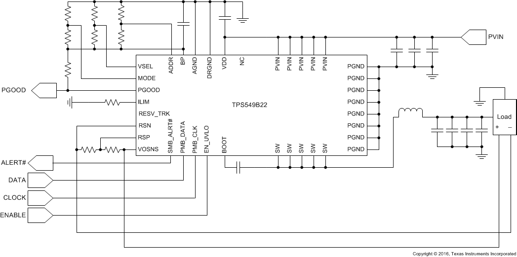
GUID-C562061A-3212-419A-B7F4-C88AA95D4D2F-low.gifアプリケーション概略図