-
TPS63802 DFN パッケージの 2A、高効率、低 IQ 昇降圧コンバータ
- 1 特長
- 2 アプリケーション
- 3 概要
- 4 Revision History
- 5 概要 (続き)
- 6 Device Comparison Table
- 7 Pin Configuration and Functions
- 8 Specifications
-
9 Detailed Description
- 9.1 Overview
- 9.2 Functional Block Diagram
- 9.3
Feature Description
- 9.3.1 Control Loop Description
- 9.3.2 Precise Device Enable: Threshold- or Delayed Enable
- 9.3.3 Mode Selection (PFM/PWM)
- 9.3.4 Undervoltage Lockout (UVLO)
- 9.3.5 Soft Start
- 9.3.6 Adjustable Output Voltage
- 9.3.7 Overtemperature Protection - Thermal Shutdown
- 9.3.8 Input Overvoltage - Reverse-Boost Protection (IVP)
- 9.3.9 Output Overvoltage Protection (OVP)
- 9.3.10 Power-Good Indicator
- 9.4 Device Functional Modes
- 10Application and Implementation
- 11Power Supply Recommendations
- 12Layout
- 13Device and Documentation Support
- 14Mechanical, Packaging, and Orderable Information
- 重要なお知らせ
DATA SHEET
TPS63802 DFN パッケージの 2A、高効率、低 IQ 昇降圧コンバータ
このリソースの元の言語は英語です。 翻訳は概要を便宜的に提供するもので、自動化ツール (機械翻訳) を使用していることがあり、TI では翻訳の正確性および妥当性につきましては一切保証いたしません。 実際の設計などの前には、ti.com で必ず最新の英語版をご参照くださいますようお願いいたします。
1 特長
- 入力電圧範囲:1.3V~5.5V
- デバイスのスタートアップ時入力電圧は 1.8V を超えること
- 出力電圧範囲:1.8V~5.2V (可変)
- 出力電流:2A (VI ≧ 2.3V、VO = 3.3V)
- 全負荷範囲にわたって高効率を実現
- 動作時の静止電流:11µA
- パワーセーブ・モードと強制 PWM モードのモード選択
- ピーク電流昇降圧モード・アーキテクチャ
- 降圧、昇降圧、昇圧動作モード間の遷移点を定義済み
- 順方向および逆方向電流動作
- あらかじめ出力にバイアスを印加した状態で起動
- 安全で堅牢な動作を実現する機能
- ソフト・スタート内蔵
- 過熱および過電圧保護
- 負荷の切り離しを伴う真のシャットダウン機能
- 順方向および逆方向の電流制限
- 小さなソリューション・サイズ:21.5mm2
- 小型の SON/DFN パッケージ (QFN と類似)
- 小型の 0.47µH インダクタ
- 最小 22µF の出力コンデンサで動作
- WEBENCH® Power Designer により、TPS63802 を使用するカスタム設計を作成
2 アプリケーション
- システム・プリレギュレータ (トラッキングおよびテレマティクス、携帯型 POS、ホーム・オートメーション、IP ネットワーク・カメラ)
- ポイント・オブ・ロード・レギュレーション (有線センサ、ポートやケーブルのアダプタとドングル、電子スマート・ロック、IoT)
- バッテリ・バックアップ電源 (電力量計、データ・コンセントレータ、電力品質メータ)
- 熱電デバイスの電源 (TEC、光モジュール)
- 汎用電圧スタビライザおよびコンバータ
3 概要
TPS63802 は、高効率で出力電流の大きい昇降圧型コンバータです。入力電圧に応じて自動的に昇圧モード、降圧モード、革新的な 4 サイクル昇降圧モード (入力電圧が出力電圧とほぼ等しい場合) のいずれかで動作します。モード間の遷移は定義されたスレッショルドで行い、出力電圧リップルを減らすためモード内での不要な切り替えは行いません。本デバイスの出力電圧は、広い出力電圧範囲内で抵抗分圧器を使用して個別に設定されます。静止電流が 11μA であるため、無負荷または軽負荷条件で最高の効率が得られます。
製品情報
| 部品番号 | パッケージ (1) | 本体サイズ (公称) |
|---|---|---|
| TPS63802 | 10 ピン VSON-HR (0.5mm ピッチ) | 3.0mm × 2.0mm |
(1) 利用可能なすべてのパッケージについては、このデータシートの末尾にある注文情報を参照してください。
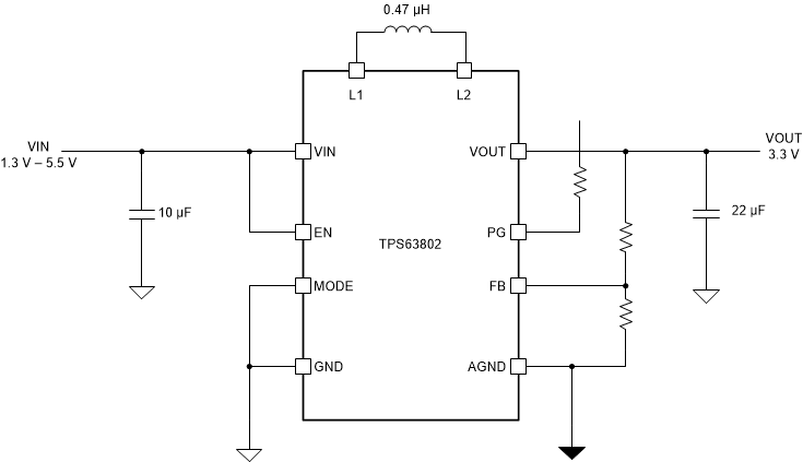
 代表的なアプリケーション
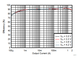
 効率と出力電流との関係 (VO = 3.3V)
4 Revision History
Changes from Revision C (June 2020) to Revision D (January 2021)
- 文書全体にわたって表、図、相互参照の採番方法を更新Go
Changes from Revision B (September 2019) to Revision C (June 2020)
- Added device comparison Go
- Changed 1x 22 µF to 2x 22 µFGo
- Changed Part Number from TPS63802RMW to TPS63802DLA Go
- Change MODE from High to Low in Application Curves Go
- Deleted layout guideline to separate AGND and PGND Go
- Deleted layout guideline to separate AGND and PGND Go
- Changed Use a common-power GND, but connect AGND and PGND through via at a different layer. to Use a common ground node for power ground and a different one for control ground to minimize the effects of ground noise. Connect these ground nodes at any place close to one of the ground pins of the IC. Go
5 概要 (続き)
TPS63802 は、1.4mm × 2.3mm の熱的に強化された HotRod™ デュアル・フラット鉛フリー (DFN) パッケージで供給されます。部品数が非常に少ないため、小さなソリューションを実現できます。