JAJSIY9D March 2020 – October 2020 TPS63900
PRODUCTION DATA
- 1 特長
- 2 アプリケーション
- 3 概要
- 4 Revision History
- 5 Pin Configuration and Functions
- 6 Specifications
-
7 Detailed Description
- 7.1 Overview
- 7.2 Functional Block Diagram
- 7.3 Feature Description
- 7.4 Device Functional Modes
- 8 Application and Implementation
- 9 Power Supply Recommendations
- 10Layout
- 11Device and Documentation Support
- 12Mechanical, Packaging, and Orderable Information
パッケージ・オプション
メカニカル・データ(パッケージ|ピン)
- DSK|10
サーマルパッド・メカニカル・データ
- DSK|10
発注情報
7.3.3 Soft Start
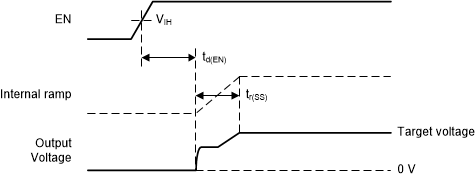
The device has a soft-start feature that starts the device typically with 500-mA peak current limit until VO = 1.8 V and 500 µs elapsed when the input current limit is set to unlimited (see Section 7.3.4). Afterwards, the output voltage ramps in a series of discrete steps (see Figure 7-6).
- When VO ≤ 1.8 V, peak current is limited to 500 mA typical for 500 µs.
- When VO > 1.8 V, each step is 100 mV high and has a duration of 125 µs.
The total soft-start ramp-up time can be calculated with Equation 2.

where
- tr(SS) is the rise time of the output voltage in milliseconds
- VO is the output voltage in volts
Figure 7-6 shows a typical start-up case.
 Figure 7-6 Start-Up Behavior
Figure 7-7 illustrates the start-up step size behavior.
 Figure 7-7 Typical Soft-Start Ramp Step Size
Table 7-1 shows the typical start-up time for a number of standard output voltages.
| OUTPUT VOLTAGE | SOFT-START RAMP-UP TIME (tr(SS)) | START-UP TIME (td(EN) + tr(SS)) |
|---|---|---|
| 1.8 V | 0.5 ms | 2 ms |
| 2.5 V | 1.375 ms | 2.875 ms |
| 3.3 V | 2.375 ms | 3.875 ms |
| 5 V | 4.5 ms | 6 ms |
If the output is prebiased – that is, the initial output voltage is not zero – the start-up behavior is as follows:
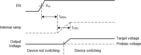
- If the prebias voltage is lower than the target voltage, the device does not start switching until the ramping output voltage is greater than the prebias voltage (see Figure 7-8).
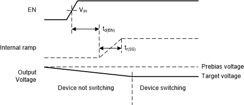
- If the prebias voltage is higher than the target voltage, the device does not start to switch until the output voltage has decreased to the target voltage (see Figure 7-9). The device cannot actively discharge the output to the target voltage and relies on the load current to discharge the output capacitor and decrease the output voltage to the target value.
 Figure 7-8 Start-Up Behavior into Prebiased (Low) Output
 Figure 7-9 Start-Up Behavior into Prebiased (High) Output