JAJSNJ1H May 2013 – December 2021 TPS65310A-Q1
PRODUCTION DATA
- 1 特長
- 2 アプリケーション
- 3 概要
- 4 Revision History
- 5 概要 (続き)
- 6 Pin Configuration and Functions
- 7 Specifications
-
8 Detailed Description
- 8.1 Overview
- 8.2 Functional Block Diagram
- 8.3 Feature Description
- 8.4
Device Functional Modes
- 8.4.1 RESET
- 8.4.2 Soft Start
- 8.4.3 INIT
- 8.4.4 TESTSTART
- 8.4.5 TESTSTOP
- 8.4.6 VTCHECK
- 8.4.7 RAMP
- 8.4.8 Power-Up Sequencing
- 8.4.9 Power-Down Sequencing
- 8.4.10 Active
- 8.4.11 ERROR
- 8.4.12 LOCKED
- 8.4.13 LPM0
- 8.4.14 Shutdown
- 8.4.15 Wake Pin
- 8.4.16 IRQ Pin
- 8.4.17 VBAT Undervoltage Warning
- 8.4.18 VIN Over Or Undervoltage Protection
- 8.4.19 External Protection
- 8.4.20 Overtemperature Detection And Shutdown
- 8.4.21 Independent Voltage Monitoring
- 8.4.22 GND Loss Detection
- 8.4.23 Reference Voltage
- 8.4.24 Shutdown Comparator
- 8.4.25 LED And High-Side Switch Control
- 8.4.26 Window Watchdog
- 8.4.27 Timeout In Start-Up Modes
- 8.5 Programming
- 8.6 Register Maps
-
9 Application and Implementation
- 9.1 Application Information
- 9.2
Typical Applications
- 9.2.1 Buck Controller 1
- 9.2.2 Synchronous Buck Converters BUCK2 and BUCK3
- 9.2.3 BOOST Converter
- 9.2.4 Linear Regulator
- 10Power Supply Recommendations
- 11Layout
- 12Device and Documentation Support
- 13Mechanical, Packaging, and Orderable Information
パッケージ・オプション
メカニカル・データ(パッケージ|ピン)
- RVJ|56
サーマルパッド・メカニカル・データ
- RVJ|56
発注情報
10 Power Supply Recommendations
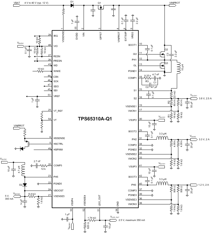
The device is designed to operate from an input voltage supply range between 4 V and 40 V (see Figure 10-1 for reference). This input supply must be well regulated. In case the supply voltage in the application is likely to exceed 40 V, the external PMOS protection device as explained in Section 8.4.19 must be applied between VIN and VINPROT pins. Furthermore, if the supply voltage in the application is likely to reach negative voltage (for example, reverse battery), a forward diode must be placed between the VSSENSE and VIN pins. A ceramic bypass capacitor with a value of 100 μF (typical) is recommended to be placed close to the VINPROT pin. For the VIN pin, a small ceramic capacitor of typical 1 µF is recommended. Also place 1-µF (typical) bypass capacitors to the DVDD and VREF pins, and 100-nF (typical) bypass capacitors to VIO pin. Furthermore, the VREG pin requires a bypass capacitor of 2.2 µF (typical).
The BUCK1 output voltage is the recommended input supply for the BUCK2, BUCK3, and BOOST regulators. Place local, 10-µF (typical) bypass capacitors at the VSUP2 and VSUP3 pins and at the supply input of the BOOST in front of the BOOST-inductor. Also place a local, 1-µF (typical) bypass capacitor at the VSUP4 pin.
The EXTSUP pin can be used to improve efficiency. For the EXTSUP pin to improve efficiency, a voltage of more than 4.8 V is required in order to have VREG regulator supplied from EXTSUP pin. If the EXSUP pin is not used, the VINPROT pin supplies the VREG regulator. The EXTSUP pin requires a 100-nF (typical) bypass capacitor.
 Figure 10-1 Typical Application Schematic