JAJSFE5C October   2009  – May 2018 TPS65720 , TPS65721

PRODUCTION DATA.  

  1. 特長
  2. アプリケーション
  3. 概要
    1.     代表的なアプリケーションの回路図
  4. 改訂履歴
  5. 概要(続き)
  6. Device Options
  7. Pin Configuration and Functions
    1.     Pin Functions—DSBGA (TPS65720)
    2.     Pin Functions—DSBGA (TPS657201, TPS657202)
    3.     Pin Functions—WQFN (TPS65721)
  8. Specifications
    1. 8.1 Absolute Maximum Ratings
    2. 8.2 ESD Ratings
    3. 8.3 Recommended Operating Conditions
    4. 8.4 Thermal Information
    5. 8.5 Electrical Characteristics
    6. 8.6 Dissipation Ratings
    7. 8.7 Timing Requirements
    8. 8.8 Switching Characteristics
    9. 8.9 Typical Characteristics
  9. Detailed Description
    1. 9.1 Overview
    2. 9.2 Functional Block Diagrams
    3. 9.3 Feature Description
      1. 9.3.1  Battery Charger and Power Path
      2. 9.3.2  Power-Path Management
      3. 9.3.3  Battery Charging
        1. 9.3.3.1 I-PRECHARGE
        2. 9.3.3.2 ITERM
        3. 9.3.3.3 Battery Detection and Recharge
        4. 9.3.3.4 Charge Termination On/Off
        5. 9.3.3.5 Timers
        6. 9.3.3.6 Dynamic Timer Function
        7. 9.3.3.7 Charger Fault
      4. 9.3.4  Thermal Regulation and Thermal Shutdown
      5. 9.3.5  Battery Pack Temperature Monitoring
      6. 9.3.6  DCDC1 Converter
      7. 9.3.7  Power Save Mode
        1. 9.3.7.1 Dynamic Voltage Positioning
        2. 9.3.7.2 Soft Start
        3. 9.3.7.3 100% Duty Cycle Low Dropout Operation
        4. 9.3.7.4 Undervoltage Lockout
      8. 9.3.8  Short-Circuit Protection
      9. 9.3.9  Thermal Shutdown
      10. 9.3.10 LDO1
        1. 9.3.10.1 Default Voltage Setting for LDOs and DCDC1
        2. 9.3.10.2 Internal Analog Multiplexer (BAT, TS, TS_OUT); TPS657201, TPS657202 Only
        3. 9.3.10.3 Internal Battery Voltage Comparator
        4. 9.3.10.4 GPIOs, LED Drivers
        5. 9.3.10.5 RESET Output
        6. 9.3.10.6 Threshold Input (TPS65721 Only)
          1. 9.3.10.6.1 ENABLE for DCDC1 and LDO1
          2. 9.3.10.6.2 PB_IN Input
          3. 9.3.10.6.3 HOLD_DCDC1 Input
          4. 9.3.10.6.4 HOLD_LDO1 Input
          5. 9.3.10.6.5 INT Output
    4. 9.4 Device Functional Modes
      1. 9.4.1 Power Down
      2. 9.4.2 Sleep Mode
      3. 9.4.3 Standby Mode
      4. 9.4.4 Power-On Reset Mode
      5. 9.4.5 Idle Mode
    5. 9.5 Programming
      1. 9.5.1 Serial Interface
    6. 9.6 Register Maps
      1. 9.6.1  CHGSTATUS Register Address: 01h (read only)
      2. 9.6.2  CHGCONFIG0 Register Address: 02h (read/write)
      3. 9.6.3  CHGCONFIG1 Register Address: 03h (read/write)
      4. 9.6.4  CHGCONFIG2 Register Address: 04h (read/write)
      5. 9.6.5  CHGCONFIG3 Register Address: 05h (read/write)
      6. 9.6.6  CHGSTATE Register Address: 06h (read only)
      7. 9.6.7  DEFDCDC1 Register Address: 07h (read/write)
      8. 9.6.8  LDO_CTRL Register Address: 08h (read/write)
      9. 9.6.9  CONTROL0 Register Address: 09h (read/write)
      10. 9.6.10 CONTROL1 Register Address: 0Ah (read/write)
      11. 9.6.11 GPIO_SSC Register Address: 0Bh (read/write)
      12. 9.6.12 GPIODIR Register Address: 0Ch (read/write)
      13. 9.6.13 IRMASK0 Register Address: 0Dh (read/write)
      14. 9.6.14 IRMASK1 Register Address: 0Eh (read/write)
      15. 9.6.15 IRMASK2 Register Address: 0Fh (read/write)
      16. 9.6.16 IR0 Register Address: 10h (read only)
      17. 9.6.17 IR1 Register Address: 11h (read)
      18. 9.6.18 IR2 Register Address: 12h (read)
  10. 10Application and Implementation
    1. 10.1 Application Information
    2. 10.2 Typical Application
      1. 10.2.1 Design Requirements
      2. 10.2.2 Detailed Design Procedure
        1. 10.2.2.1 Output Voltage Setting
          1. 10.2.2.1.1 DCDC1
          2. 10.2.2.1.2 LDO1
        2. 10.2.2.2 Output Filter Design (Inductor and Output Capacitor)
          1. 10.2.2.2.1 Inductor Selection
          2. 10.2.2.2.2 Output Capacitor Selection
          3. 10.2.2.2.3 Input Capacitor Selection
        3. 10.2.2.3 Charger/Power Path
          1. 10.2.2.3.1 Charger Stability
          2. 10.2.2.3.2 Setting the Charge Current
          3. 10.2.2.3.3 Dynamic Power Path Management (DPPM)
      3. 10.2.3 Application Curves
  11. 11Power Supply Recommendations
  12. 12Layout
    1. 12.1 Layout Guidelines
    2. 12.2 Layout Example
  13. 13デバイスおよびドキュメントのサポート
    1. 13.1 デバイス・サポート
      1. 13.1.1 デベロッパー・ネットワークの製品に関する免責事項
    2. 13.2 ドキュメントのサポート
      1. 13.2.1 関連資料
    3. 13.3 関連リンク
    4. 13.4 ドキュメントの更新通知を受け取る方法
    5. 13.5 コミュニティ・リソース
    6. 13.6 商標
    7. 13.7 静電気放電に関する注意事項
    8. 13.8 Glossary
  14. 14メカニカル、パッケージ、および注文情報

パッケージ・オプション

メカニカル・データ(パッケージ|ピン)
サーマルパッド・メカニカル・データ
発注情報

概要

TPS6572xデバイスは小型の電源管理ユニットで、Bluetooth対応ヘッドセットなど、低消費電力の携帯型消費者向け最終機器を対象としています。このデバイスにはUSBフレンドリなリチウムイオン・バッテリ充電器、高効率の降圧コンバータ、低ドロップアウトのリニア・レギュレータ、および追加サポート機能が含まれています。このデバイスは、I2Cインターフェイスにより制御されます。不揮発性メモリを使用して、出荷時プログラムにより、いくつかの設定をカスタマイズできます。

2.25MHz降圧コンバータは、軽負荷時には低消費電力モードへ移行し、可能な限り広い負荷電流の範囲にわたって最大の効率を維持します。低ノイズのアプリケーションでは、I2C互換インターフェイスを使用して、デバイスを強制的に固定周波数のPWMモードに設定できます。

製品情報 (1)

型番 パッケージ 本体サイズ(公称)
TPS65720x DSBGA (25) 2.11mm×2.11mm
TPS65721 WQFN (32) 4.00mm×4.00mm
  1. 提供されているすべてのパッケージについては、データシートの末尾にある注文情報を参照してください。

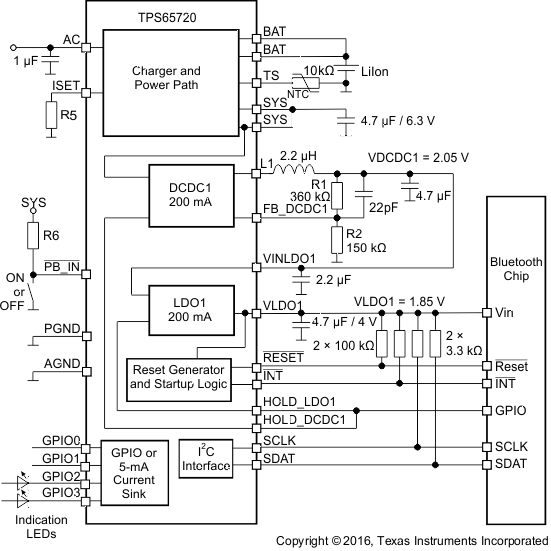
代表的なアプリケーションの回路図
TPS65720 TPS657201 TPS657202 TPS65721 alt_slvs979.gif