JAJS189U January 2006 – September 2024 TPS737
PRODUCTION DATA
- 1
- 1 特長
- 2 アプリケーション
- 3 概要
- 4 Pin Configuration and Functions
- 5 Specifications
- 6 Detailed Description
- 7 Application and Implementation
- 8 Device and Documentation Support
- 9 Revision History
- 10Mechanical, Packaging, and Orderable Information
パッケージ・オプション
デバイスごとのパッケージ図は、PDF版データシートをご参照ください。
メカニカル・データ(パッケージ|ピン)
- DCQ|6
- DRV|6
- DRB|8
サーマルパッド・メカニカル・データ
発注情報
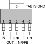
4 Pin Configuration and Functions
 Figure 4-1 DCQ Package,6-Pin SOT-223(Top View)

A. Power dissipation can limit
operating range. Check the Thermal Information table.
Figure 4-3 DRV Package(A),6-Pin WSON(Top View)
Table 4-1 Pin Functions
| PIN | Type(1) | DESCRIPTION | |||
|---|---|---|---|---|---|
| NAME | SOT-223 | VSON | WSON | ||
| IN | 1 | 8 | 6 | I | Unregulated input supply |
| GND | 3, 6 | 4, Pad | 3, Pad | — | Ground |
| EN | 5 | 5 | 4 | I | Driving the enable pin (EN) high turns on the regulator. Driving this pin low puts the regulator into shutdown mode. See the Section 6.3.3 section for more details. EN must not be left floating and can be connected to IN if not used. |
| NR | 4 | 3 | 2 | — | Fixed voltage versions only—connecting an external capacitor to this pin bypasses noise generated by the internal band gap, reducing output noise to very low levels. |
| FB | 4 | 3 | 2 | I | Adjustable voltage version only—this is the input to the control loop error amplifier, and is used to set the output voltage of the device. |
| OUT | 2 | 1 | 1 | O | Regulator output. A 1.0-μF or larger capacitor of any type is required for stability. |
| NC | — | 2, 6, 7 | 5 | — | Not connected |
(1) I = Input; O = Output