JAJSH81B April 2019 – February 2021 TPS929120-Q1
PRODUCTION DATA
- 1 特長
- 2 アプリケーション
- 3 概要
- 4 Revision History
- 5 Pin Configuration and Functions
- 6 Specifications
-
7 Detailed Description
- 7.1 Overview
- 7.2 Functional Block Diagram
- 7.3
Feature Description
- 7.3.1 Device Bias and Power
- 7.3.2 Constant Current Output
- 7.3.3 PWM Dimming
- 7.3.4 On-chip 8-bit Analog-to-Digital Converter (ADC)
- 7.3.5
Diagnostic and Protection in Normal State
- 7.3.5.1 Fault Masking
- 7.3.5.2 Supply Undervoltage Lockout Diagnostics in Normal State
- 7.3.5.3 Low-Supply Warning Diagnostics in Normal State
- 7.3.5.4 Reference Diagnostics in Normal State
- 7.3.5.5 Pre-Thermal Warning and Overtemperature Protection in Normal State
- 7.3.5.6 Communication Loss Diagnostic in Normal State
- 7.3.5.7 LED Open-Circuit Diagnostics in Normal State
- 7.3.5.8 LED Short-circuit Diagnostics in Normal State
- 7.3.5.9 On-Demand Off-State Invisible Diagnostics
- 7.3.5.10 On-Demand Off-State Single-LED Short-Circuit (SS) Diagnostics
- 7.3.5.11 Automatic Single-LED Short-Circuit (AutoSS) Detection in Normal State
- 7.3.5.12 EEPROM CRC Error in Normal State
- 47
- 7.3.6
Diagnostic and Protection in Fail-Safe States
- 7.3.6.1 Fault Masking
- 7.3.6.2 Supply UVLO Diagnostics in Fail-Safe States
- 7.3.6.3 Low-supply Warning Diagnostics in Fail-Safe states
- 7.3.6.4 Reference Diagnostics at Fail-Safe States
- 7.3.6.5 Overtemperature Protection in Fail-Safe State
- 7.3.6.6 LED Open-circuit Diagnostics in Fail-Safe State
- 7.3.6.7 LED Short-circuit Diagnostics in Fail-safe State
- 7.3.6.8 EEPROM CRC Error in Fail-safe State
- 57
- 7.4 Device Functional Modes
- 7.5 Programming
- 7.6 Register Maps
- 8 Application and Implementation
- 9 Power Supply Recommendations
- 10Layout
- 11Device and Documentation Support
- 12Mechanical, Packaging, and Orderable Information
パッケージ・オプション
メカニカル・データ(パッケージ|ピン)
- PWP|24
サーマルパッド・メカニカル・データ
- PWP|24
発注情報
3 概要
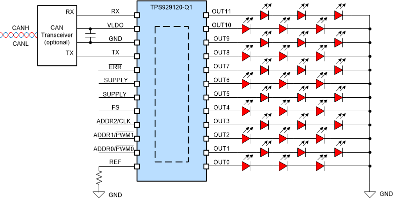
車載用照明のアニメーション化の要求が増大していることから、LED を独立して制御する必要があります。それにより、ピクセル制御の照明アプリケーションを効果的に駆動するために、デジタル・インターフェイスを持つ LED ドライバが不可欠です。外装用照明では、複数のランプ機能が通常別々の PCB 基板に搭載されており、オフボード配線で互いに接続されています。従来型のシングルエンド・インターフェイスでは、厳しい EMC 要件を満たすことは困難です。TPS929120-Q1 の UART ベースの FlexWire インターフェイスは、業界標準の CAN 物理層を使用することで、EMC に影響を及ぼすことなくオフボードの長距離通信を簡単に実現できます。
TPS929120-Q1 は、8 ビットの出力電流と 12 ビットの PWM デューティ・サイクルを制御する 12 チャネル、40V ハイサイド LED ドライバです。本デバイスは、LED の断線、グランドへの短絡、単一 LED の短絡診断機能によって、複数のレギュレーション要件を満たしています。また、構成可能なウォッチドッグにより、MCU 接続が失われた場合に自動的にフェイルセーフ状態を設定します。さらにプログラム可能な EEPROM を使い、各種アプリケーション・シナリオに応じて TPS929120-Q1 を柔軟に設定できます。
製品情報(1)
| 部品番号 | パッケージ | 本体サイズ (公称) |
|---|---|---|
| TPS929120-Q1 | HTSSOP (24) | 7.80mm × 4.40mm |
(1) 利用可能なすべてのパッケージについては、このデータシートの末尾にある注文情報を参照してください。
 代表的なアプリケーションの図