JAJSHV7F August 2019 – November 2021 TPSM82821 , TPSM82821A , TPSM82822 , TPSM82822A , TPSM82823 , TPSM82823A
PRODUCTION DATA
- 1 特長
- 2 アプリケーション
- 3 概要
- 4 Revision History
- 5 Device Comparison Table
- 6 Pin Configuration and Functions
- 7 Specifications
- 8 Detailed Description
- 9 Application and Implementation
- 10Power Supply Recommendations
- 11Layout
- 12Device and Documentation Support
パッケージ・オプション
デバイスごとのパッケージ図は、PDF版データシートをご参照ください。
メカニカル・データ(パッケージ|ピン)
- SIL|10
サーマルパッド・メカニカル・データ
発注情報
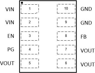
6 Pin Configuration and Functions
 Figure 6-1 µSiL Package(Top View)
Table 6-1 Pin Functions
| PIN | I/O | DESCRIPTION | |
|---|---|---|---|
| NAME | NO. | ||
| EN | 3 | I | Device enable pin. To enable the device, this pin needs to be pulled high. Pulling this pin low disables the device. Do not leave floating. |
| FB | 8 | I | Feedback pin. This pin must be connected to the center of the output voltage resistor divider. For the fixed output voltage devices, connect this pin directly to the output voltage. |
| GND | 9, 10 | PWR | Ground pin |
| PG | 4 | O | Power-good open-drain output pin with window comparator. The pullup resistor can be connected to voltages up to 5.5 V. If unused, leave it floating. |
| VIN | 1, 2 | PWR | Input voltage pin |
| VOUT | 5, 6, 7 | PWR | Output voltage pin |