JAJSE92B
November 2017 – April 2018
TPSM84824
PRODUCTION DATA.
1
特長
2
アプリケーション
概略回路図
3
概要
過渡応答
4
改訂履歴
5
Pin Configuration and Functions
Pin Functions
6
Specifications
6.1
Absolute Maximum Ratings
6.2
ESD Ratings
6.3
Recommended Operating Conditions
6.4
Thermal Information
6.5
Electrical Characteristics
6.6
Switching Characteristics
6.7
Typical Characteristics (VIN = 12 V)
6.8
Typical Characteristics (VIN = 5 V)
7
Detailed Description
7.1
Overview
7.2
Functional Block Diagram
7.3
Feature Description
7.3.1
Adjusting the Output Voltage
7.3.2
Switching Frequency (RT)
7.3.3
Synchronization (CLK)
7.3.4
Output On/Off Enable (EN)
7.3.5
Input Capacitor Selection
7.3.6
Output Capacitor Selection
7.3.7
TurboTrans (TT)
7.3.7.1
Low-ESR Output Capacitors
7.3.7.2
Transient Response
7.3.7.2.1
Transient Waveforms (VIN = 12 V)
7.3.8
Undervoltage Lockout (UVLO)
7.3.9
Soft Start (SS/TR)
7.3.10
Sequencing (SS/TR)
7.3.11
Power Good (PGOOD)
7.3.12
Safe Start-up into Pre-Biased Outputs
7.3.13
Overcurrent Protection
7.3.14
Thermal Shutdown
7.4
Device Functional Modes
7.4.1
Active Mode
7.4.2
Shutdown Mode
8
Application and Implementation
8.1
Application Information
8.2
Typical Application
8.2.1
Design Requirements
8.2.2
Detailed Design Procedure
8.2.2.1
Custom Design With WEBENCH® Tools
8.2.2.2
Output Voltage Setpoint
8.2.2.3
Setting the Switching Frequency
8.2.2.4
Input Capacitors
8.2.2.5
Output Capacitors
8.2.2.6
TurboTrans Resistor
8.2.2.7
Application Waveforms
9
Power Supply Recommendations
10
Layout
10.1
Layout Guidelines
10.2
Layout Examples
10.3
EMI
10.3.1
EMI Plots
10.4
Package Specifications
11
デバイスおよびドキュメントのサポート
11.1
デバイス・サポート
11.1.1
デベロッパー・ネットワークの製品に関する免責事項
11.1.2
開発サポート
11.1.2.1
WEBENCH®ツールによるカスタム設計
11.2
ドキュメントの更新通知を受け取る方法
11.3
コミュニティ・リソース
11.4
商標
11.5
静電気放電に関する注意事項
11.6
Glossary
12
メカニカル、パッケージ、および注文情報
パッケージ・オプション
メカニカル・データ(パッケージ|ピン)
MOL|24
MPQF489
サーマルパッド・メカニカル・データ
発注情報
jajse92b_oa
6.8
Typical Characteristics (V
IN
= 5 V)
T
A
= 25°C, unless otherwise noted.
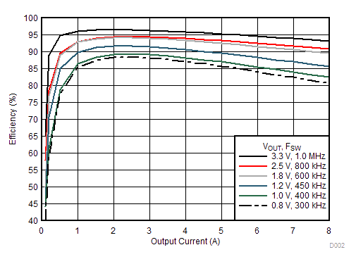
Figure 7.
Efficiency vs Output Current
V
OUT
= 1.2 V
f
SW
= 450 kHz
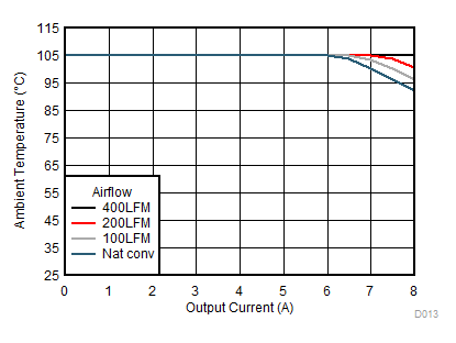
Figure 9.
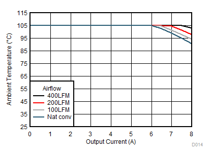
Safe Operating Area
V
OUT
= 3.3 V
f
SW
= 1 MHz
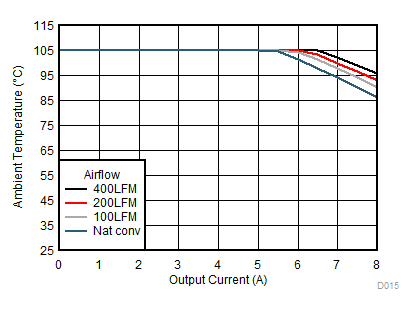
Figure 11.
Safe Operating Area
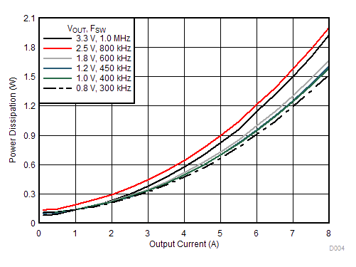
Figure 8.
Power Dissipation vs Output Current
V
OUT
= 1.8 V
f
SW
= 600 kHz
Figure 10.
Safe Operating Area