JAJSH31C November 2014 – March 2019 TS3DDR4000
PRODUCTION DATA.
8.2 Functional Block Diagram
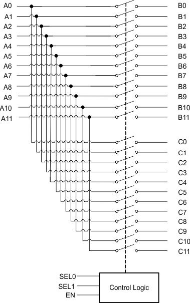
The following diagram (Figure 18) represents the switch function block diagram of the TS3DDR4000. Port A (A0-A11) can be routed to either port B (B0-B11) or port C (C0-C11) by configuring the SEL0 and SEL1 pins. The EN pin can be toggled high to put the device into the low-power mode with minimal power consumption.
