JAJSC34B March 2012 – December 2023 UCC28070A
PRODUCTION DATA
- 1
- 1 特長
- 2 アプリケーション
- 3 概要
- 4 Pin Configuration and Functions
- 5 Specifications
-
6 Detailed Description
- 6.1 Overview
- 6.2 Functional Block Diagram
- 6.3
Feature Description
- 6.3.1 Interleaving
- 6.3.2 Programming the PWM Frequency and Maximum Duty-Cycle Clamp
- 6.3.3 Frequency Dithering (Magnitude and Rate)
- 6.3.4 External Clock Synchronization
- 6.3.5 Multi-phase Operation
- 6.3.6 VSENSE and VINAC Resistor Configuration
- 6.3.7 VSENSE and VINAC Open-Circuit Protection
- 6.3.8 Current Synthesizer
- 6.3.9 Programmable Peak Current Limit
- 6.3.10 Linear Multiplier and Quantized Voltage Feed Forward
- 6.3.11 Enhanced Transient Response (VA Slew-Rate Correction)
- 6.3.12 Voltage Biasing (VCC and VVREF)
- 6.3.13 PFC Enable and Disable
- 6.3.14 Adaptive Soft Start
- 6.3.15 PFC Start-Up Hold Off
- 6.3.16 Output Overvoltage Protection (OVP)
- 6.3.17 Zero-Power Detection
- 6.3.18 Thermal Shutdown
- 6.3.19 Current Loop Compensation
- 6.3.20 Voltage Loop Compensation
- 6.4 Device Functional Modes
-
7 Application and Implementation
- 7.1 Application Information
- 7.2
Typical Application
- 7.2.1 Design Requirements
- 7.2.2
Detailed Design Procedure
- 7.2.2.1 Output Current Calculation
- 7.2.2.2 Bridge Rectifier
- 7.2.2.3 PFC Inductor (L1 and L2)
- 7.2.2.4 PFC MOSFETs (M1 and M2)
- 7.2.2.5 PFC Diode
- 7.2.2.6 PFC Output Capacitor
- 7.2.2.7 Current-Loop Feedback Configuration (Sizing of the Current-Transformer Turns-Ratio and Sense Resistor (RS))
- 7.2.2.8 Current-Sense Offset and PWM Ramp for Improved Noise Immunity
- 7.2.3 Application Curves
- 7.3 Power Supply Recommendations
- 7.4 Layout
- 8 Device and Documentation Support
- 9 Revision History
- 10Mechanical, Packaging, and Orderable Information
3 概要
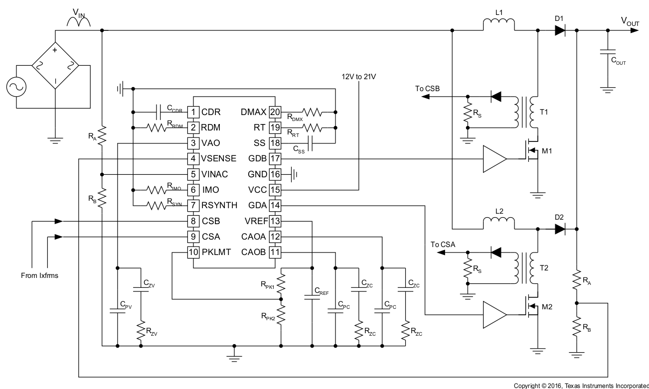
UCC28070A は、UCC28070 を基本として周波数範囲を拡張した製品であり、大電力アプリケーションで IGBT 電源スイッチをベースとした PFC コンバータに要求される低スイッチング周波数で動作可能です。
UCC28070Aは、10kHz~300kHzの周波数で動作可能なため、最低動作周波数が30kHzであるUCC28070よりも広い範囲で動作できます。UCC28070の他の機能および利点はすべて、UCC28070Aでも利用できます。180°位相のずれたインターリーブ動作により、入出力のリップル電流が大幅に減少し、EMIフィルタを容易に低コストで実装できます。
UCC28070と同様に、UCC28070Aにも、電流合成や段階的に補正されるVff機能など、いくつもの革新的な機能が搭載されているため、力率、効率、THD、過渡応答の性能が向上しています。周波数ディザリング、クロック同期、スルーレート向上などにより、性能の改善の可能性を広げています。出力過電圧検出、プログラム可能なピーク電流制限、低電圧誤動作防止、開ループ保護など、UCC28070のすべての保護機能は、UCC28070Aでも利用できます。
製品情報
| 部品番号 | パッケージ | 本体サイズ(公称) |
|---|---|---|
| UCC28070A | TSSOP (20) | 6.50mm × 4.40mm |
 アプリケーション概略図