JAJSKM1C october 2019 – september 2021 UCC5870-Q1
PRODUCTION DATA
- 1
- 1 特長
- 2 アプリケーション
- 3 概要
- 4 Revision History
- 5 Pin Configuration and Functions
- 6 Specifications
-
7 Detailed Description
- 7.1 Overview
- 7.2 Functional Block Diagram
- 7.3
Feature Description
- 7.3.1 Power Supplies
- 7.3.2 Driver Stage
- 7.3.3 Integrated ADC for Front-End Analog (FEA) Signal Processing
- 7.3.4 Fault and Warning Classification
- 7.3.5
Diagnostic Features
- 7.3.5.1 Undervoltage Lockout (UVLO) and Overvoltage Lockout (OVLO)
- 7.3.5.2 CLAMP, OUTH, and OUTL Clamping Circuits
- 7.3.5.3 Active Miller Clamp
- 7.3.5.4 DESAT based Short Circuit Protection (DESAT)
- 7.3.5.5 Shunt Resistor based Overcurrent Protection (OCP) and Short Circuit Protection (SCP)
- 7.3.5.6 Temperature Monitoring and Protection for the Power Transistors
- 7.3.5.7 Active High Voltage Clamping (VCECLP)
- 7.3.5.8 Two-Level Turn-Off
- 7.3.5.9 Soft Turn-Off (STO)
- 7.3.5.10 Thermal Shutdown (TSD) and Temperature Warning (TWN) of Driver IC
- 7.3.5.11 Active Short Circuit Support (ASC)
- 7.3.5.12 Shoot-Through Protection (STP)
- 7.3.5.13 Gate Voltage Monitoring and Status Feedback
- 7.3.5.14 VGTH Monitor
- 7.3.5.15 Cyclic Redundancy Check (CRC)
- 7.3.5.16 Configuration Data CRC
- 7.3.5.17 SPI Transfer Write/Read CRC
- 7.3.5.18 TRIM CRC Check
- 7.4 Device Functional Modes
- 7.5 Programming
- 7.6 Register Maps
- 8 Applications and Implementation
- 9 Power Supply Recommendations
- 10Layout
- 11Device and Documentation Support
- 12Mechanical, Packaging, and Orderable Information
7.3.5.7 Active High Voltage Clamping (VCECLP)
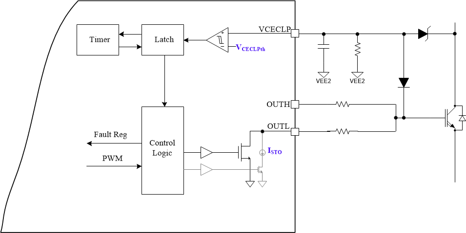
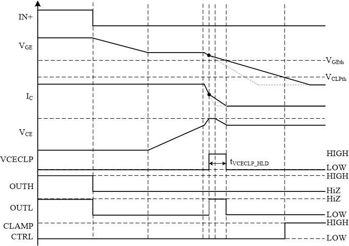
The active high voltage clamping feature protects power transistors from over-voltage damage during switching transitions, while reducing the power dissipated in the external TVS clamp diodes protecting the power FET. During turn-off, the VCECLP input is monitored. Once the VCE of the FET increases to turn on the external TVS diode, the RC network on the VCECLP input is charged up. Once the VCECLP input reaches the clamp threshold (VCECLPTH), OUTL drive strength changes to the ISTO setting in order to slow down the turn off and reduce the overshoot. The high voltage clamping remains active for a predefined time tVCECLP_HLD. The OV condition is reported in STATUS3[VCEOV_FAULT] (STATUS3). The implementation and timing diagrams for the active high voltage clamping are presented in Figure 7-22 and Figure 7-23, respectively. The VCECLP feature is enabled/disabled using the CFG4[VCECLP_EN] bit (CFG4).
 Figure 7-22 Block diagram of implementation of
active high voltage clamping function.
 Figure 7-23 Timing scheme of implementation of
active high voltage clamping function.