JAJSKM1C october 2019 – september 2021 UCC5870-Q1
PRODUCTION DATA
- 1
- 1 特長
- 2 アプリケーション
- 3 概要
- 4 Revision History
- 5 Pin Configuration and Functions
- 6 Specifications
-
7 Detailed Description
- 7.1 Overview
- 7.2 Functional Block Diagram
- 7.3
Feature Description
- 7.3.1 Power Supplies
- 7.3.2 Driver Stage
- 7.3.3 Integrated ADC for Front-End Analog (FEA) Signal Processing
- 7.3.4 Fault and Warning Classification
- 7.3.5
Diagnostic Features
- 7.3.5.1 Undervoltage Lockout (UVLO) and Overvoltage Lockout (OVLO)
- 7.3.5.2 CLAMP, OUTH, and OUTL Clamping Circuits
- 7.3.5.3 Active Miller Clamp
- 7.3.5.4 DESAT based Short Circuit Protection (DESAT)
- 7.3.5.5 Shunt Resistor based Overcurrent Protection (OCP) and Short Circuit Protection (SCP)
- 7.3.5.6 Temperature Monitoring and Protection for the Power Transistors
- 7.3.5.7 Active High Voltage Clamping (VCECLP)
- 7.3.5.8 Two-Level Turn-Off
- 7.3.5.9 Soft Turn-Off (STO)
- 7.3.5.10 Thermal Shutdown (TSD) and Temperature Warning (TWN) of Driver IC
- 7.3.5.11 Active Short Circuit Support (ASC)
- 7.3.5.12 Shoot-Through Protection (STP)
- 7.3.5.13 Gate Voltage Monitoring and Status Feedback
- 7.3.5.14 VGTH Monitor
- 7.3.5.15 Cyclic Redundancy Check (CRC)
- 7.3.5.16 Configuration Data CRC
- 7.3.5.17 SPI Transfer Write/Read CRC
- 7.3.5.18 TRIM CRC Check
- 7.4 Device Functional Modes
- 7.5 Programming
- 7.6 Register Maps
- 8 Applications and Implementation
- 9 Power Supply Recommendations
- 10Layout
- 11Device and Documentation Support
- 12Mechanical, Packaging, and Orderable Information
7.3.1.7 Other Internal Rails
There are several internal rails that are used to power the device. All of the internal rails are monitored for OV and UV conditions. Any OV/UV faults are recorded in the STATUS2[INT_REG_PRI_FAULT] (STATUS2) and STATUS3[INT_REG_SEC_FAULT] (STATUS3) bits.
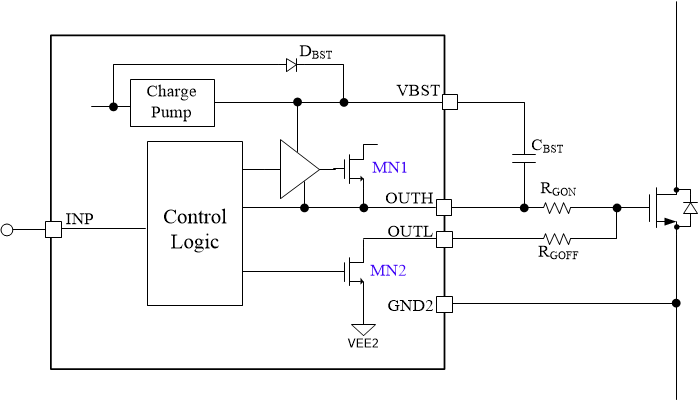
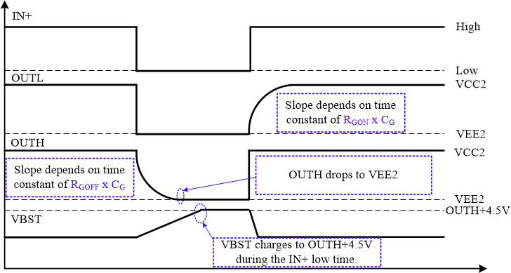
Bootstrap (VBST) and charge pump circuits generate the 4.5V power supply for the high side NMOS of internal driver stage. The implementation diagram is shown in Figure 7-1. The external cap on BST is charged to 4.5V while OUTL is on (MN2 is on). While OUTH is on (MN1 is on), the capacitor voltage is stacked above OUTH and supplies the gate drive for the high-side NMOS. Under most conditions, the bootstrap circuit is used and the timing operates as shown in Figure 7-2. However, for slow switching frequencies at high duty cycles the external capacitor may not be able to charge enough during the OUTH off time to supply the gate drive for the entire on-time. In these conditions, the charge pump circuit is used to hold the voltage across the bootstrap capacitor. .
 Figure 7-1 Implementation diagram of bootstrap and charge pump circuits.
 Figure 7-2 Timing diagram of bootstrap circuit.