-
ADS1257 30-kSPS, 4-Channel, 24-Bit ADC with PGA in 5-mm × 5-mm VQFN Package
- 1 Features
- 2 Applications
- 3 Description
- 4 Revision History
- 5 Device Comparison Table
- 6 Pin Configuration and Functions
-
7 Specifications
- 7.1 Absolute Maximum Ratings
- 7.2 ESD Ratings
- 7.3 Recommended Operating Conditions
- 7.4 Thermal Information
- 7.5 Electrical Characteristics
- 7.6 Serial Interface Timing Requirements
- 7.7 Serial Interface Switching Characteristics
- 7.8 RESET and SYNC/PWDN Timing Requirements
- 7.9 SCLK Reset Timing Requirements
- 7.10 DRDY Update Timing Characteristics
- 7.11 Typical Characteristics
- 8 Parameter Measurement Information
-
9 Detailed Description
- 9.1 Overview
- 9.2 Functional Block Diagram
- 9.3
Feature Description
- 9.3.1 Input Multiplexer
- 9.3.2 Analog Input Buffer
- 9.3.3 Programmable Gain Amplifier (PGA)
- 9.3.4 Modulator Input Circuitry
- 9.3.5 Voltage Reference Inputs (REFP, REFN)
- 9.3.6 Clock Input (CLKIN)
- 9.3.7 Clock Output (D0/CLKOUT)
- 9.3.8 General-Purpose Digital I/O (D0, D1)
- 9.3.9 Open- and Short-Circuit Sensor Detection
- 9.3.10 Digital Filter
- 9.4 Device Functional Modes
- 9.5
Programming
- 9.5.1 Serial Interface
- 9.5.2 Data Format
- 9.5.3
Command Definitions
- 9.5.3.1 WAKEUP/NOP: Complete Synchronization or Exit Standby Mode
- 9.5.3.2 RDATA: Read Data
- 9.5.3.3 RDATAC: Read Data Continuous
- 9.5.3.4 SDATAC: Stop Read Data Continuous
- 9.5.3.5 RREG: Read from Registers
- 9.5.3.6 WREG: Write to Register
- 9.5.3.7 SELFCAL: Self-Offset and Self-Gain Calibration
- 9.5.3.8 SELFOCAL: Self Offset Calibration
- 9.5.3.9 SELFGCAL: Self Gain Calibration
- 9.5.3.10 SYSOCAL: System Offset Calibration
- 9.5.3.11 SYSGCAL: System Gain Calibration
- 9.5.3.12 STANDBY: Standby Mode / Single-shot Mode
- 9.5.3.13 RESET: Reset Registers to Default Values
- 9.5.3.14 SYNC: Synchronize the Analog-to-Digital Conversion
- 9.6
Register Map
- 9.6.1 STATUS: Status Register (address = 00h) [reset = x1h]
- 9.6.2 MUX : Input Multiplexer Control Register (address = 01h) [reset = 01h]
- 9.6.3 ADCON: ADC Control Register (address = 02h) [reset = 20h]
- 9.6.4 DRATE: ADC Data Rate Register (address = 03h) [reset = F0h]
- 9.6.5 IO: GPIO Control Register (address = 04h) [reset = E0h]
- 9.6.6 OFC0: Offset Calibration Register 0 (address = 05h) [reset = depends on calibration results]
- 9.6.7 OFC1: Offset Calibration Register 1 (address = 06h) [reset = depends on calibration results]
- 9.6.8 OFC2: Offset Calibration Register 2 (address = 07h) [reset = depends on calibration results]
- 9.6.9 FSC0: Full-Scale Calibration Register 0 (address = 08h) [reset = depends on calibration results]
- 9.6.10 FSC1: Full-Scale Calibration Register 1 (address = 09h) [reset = depends on calibration results]
- 9.6.11 FSC2: Full-Scale Calibration Register 2 (address = 0Ah) [reset = depends on calibration results]
- 10Applications and Implementation
- 11Power Supply Recommendations
- 12Layout
- 13Device and Documentation Support
- 14Mechanical, Packaging, and Orderable Information
- IMPORTANT NOTICE
パッケージ・オプション
メカニカル・データ(パッケージ|ピン)
- RGW|20
サーマルパッド・メカニカル・データ
- RGW|20
発注情報
ADS1257 30-kSPS, 4-Channel, 24-Bit ADC with PGA in 5-mm × 5-mm VQFN Package
1 Features
- Up to 23-Bits Noise-Free Resolution
- Small 5-mm × 5-mm VQFN Package
- 4 Analog Inputs
- 2 Differential or 3 Single-Ended Measurements
- Excellent DC Performance
- Offset Drift: 4 nV/°C (Gain = 64)
- Gain Drift: 0.8 ppm/°C
- Nonlinearity: 3 ppm (Gain = 1)
- Programmable Data Rates: 2.5 SPS to 30 kSPS
- Single-Cycle Settled Conversions (≤ 1000 SPS)
- 50-Hz and 60-Hz Rejection
- High Impedance Input Buffer
- Differential-Input PGA
- Integrated Sensor Break Detection
- 2 General-Purpose Input/Outputs
- Power Supplies:
- Analog: 5 V
- Digital: 1.8 V to 3.6 V
- 5-V Tolerant SPI™-Compatible Serial Interface
2 Applications
- Factory Automation and Process Control
- Test and Measurement
- Medical Equipment
- Scientific Instrumentation
3 Description
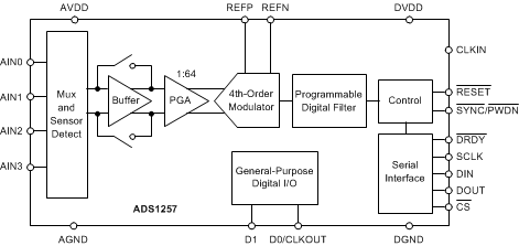
The ADS1257 is a low-noise, 30-kSPS, 24-bit, delta-sigma (ΔΣ) analog-to-digital converter (ADC) with an integrated multiplexer (mux), input buffer, and programmable gain amplifier (PGA) in a small 20-pin, 5-mm × 5-mm VQFN package. The combination of integration, high conversion rate, and 24-bit resolution together in a small package makes the device ideally suited for space-constrained applications.
The input multiplexer accepts either two differential or three single-ended input measurements. The sensor-break detection circuit verifies the input connection continuity to the ADC. The selectable input buffer greatly increases the input impedance, and in many cases, eliminates the need for external buffers. The buffer input voltage range includes AGND. The low-noise PGA provides gains from 1 to 64 to accommodate a wide range of inputs signals. The programmable digital filter optimizes ADC resolution (up to 23 bits noise-free) and conversion rates (up to 30 kSPS). The digital filter provides single-cycle settled conversions, and rejection of 50-Hz and 60-Hz interference signals.
The SPI-compatible serial interface operates with as little as three wires, simplifying connections to external controllers. Integrated calibration features support both self and system correction of offset and gain errors for all PGA gain settings. Two bidirectional digital I/Os pins control external circuits.
Device Information(1)
| PART NUMBER | PACKAGE | BODY SIZE (NOM) |
|---|---|---|
| ADS1257 | VQFN (20) | 5.00 mm × 5.00 mm |
- For all available packages, see the package option addendum at the end of the data sheet.
4 Revision History
Changes from A Revision (October 2015) to B Revision
- Changed front-page diagram; removed clock generator block for clarityGo
- Changed all instances of "PDWN" to "PWDN" for consistencyGo
- Changed Recommended Operating Conditions "Specified ambient temperature" to "Operating ambient temperature, TA" for clarityGo
- Added Timing Requirements and Switching Characteristics tables along with associated figures, and Typical Characteristics, Parameter Measurement Information, Detailed Description, Applications and Implementation, Power Supply Recommendations, and Layout sectionsGo
Changes from * Revision (September 2015) to A Revision
- Changed from product preview to production dataGo
6 Pin Configuration and Functions
Pin Functions
| PIN | I/O | DESCRIPTION | |
|---|---|---|---|
| NO. | NAME | ||
| 1 | REFP | Analog input | Positive reference input |
| 2 | AIN0 | Analog input | Analog input 0; Leave unconnected or connect to AVDD if not used(4) |
| 3 | AIN1 | Analog input | Analog input 1; Leave unconnected or connect to AVDD if not used(4) |
| 4 | AIN2 | Analog input | Analog input 2; Leave unconnected or connect to AVDD if not used(4) |
| 5 | AIN3 | Analog input | Analog input 3; Leave unconnected or connect to AVDD if not used(4) |
| 6 | SYNC/PWDN | Digital input(1)(2) | Synchronization or power-down input, active low; Connect to DVDD if not used(4) |
| 7 | RESET | Digital input(1)(2) | Reset input, active low; Connect to DVDD if not used(4) |
| 8 | DVDD | Digital | Digital power supply; Connect decoupling capacitor to DGND |
| 9 | DGND | Digital | Digital ground |
| 10 | CLKIN | Digital input(2) | External clock input |
| 11 | CS | Digital input(1)(2) | Chip select, active low; Connect to DGND if not used |
| 12 | DRDY | Digital output | Data ready output; active low |
| 13 | DOUT | Digital output | Serial data output |
| 14 | DIN | Digital input(1)(2) | Serial data input |
| 15 | SCLK | Digital input(1)(2) | Serial clock input |
| 16 | D0/CLKOUT | Digital input/output(3) | General-purpose digital I/O 0 or clock output(4) |
| 17 | D1 | Digital input/output(3) | General-purpose digital I/O 1(4) |
| 18 | AVDD | Analog | Analog power supply; Connect decoupling capacitor to AGND |
| 19 | AGND | Analog | Analog ground |
| 20 | REFN | Analog input | Negative reference input |
| Thermal Pad | — | Thermal power pad; Connect to AGND | |

