DLPU131A November 2023 – September 2024
2.3 Setup
Use the following instructions to set up and run the DLPDLCR160CPEVM. A 5V power adapter with a 1A minimum output and a USB-C connector is required.
Table 2-1 Steps to Use the EVM
| Step | Action | Comments |
|---|---|---|
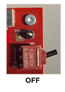
| Power switch (SW1) at OFF position | Power switch (Figure 2-1), SW1, needs to be in the OFF position before power is turned ON to the board. Toggle lever to the OFF position, opposite direction of the arrow shown on the board. | TI does not recommend to pull out the power cable or turn off the input power while the EVM is running. The SW1 switch is also used to turn off the EVM before the input power is turned off. |
 | ||
| Connect power supply | Connect a USB-C power supply supporting 5V at 1A. | Note: Do not use a muti-voltage output USB-C power adapter. |
| LED D1 turns on | The green LED, D1, lights up to indicate the board is receiving power. | |
| Power switch (SW1) ON | Power switch (SW1) to the ON position in the direction of the arrow on the board. | 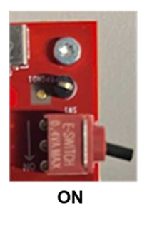 |
| LED D2 turns on | The green LED, D2, lights up to indicate the board is in operational mode. | The RGB LEDs in the Optical Engine (OE) are turned on. |
| Splash Screen |
The EVM shows a DLP Logo as a quick power up slash screen for approximately 1 second. |  |
| DLP logo animation | A DLP Logo animation using graphics generated by the MCU plays for approximately 5 seconds. |  |
| Main menu | A user selectable main menu is displayed. | 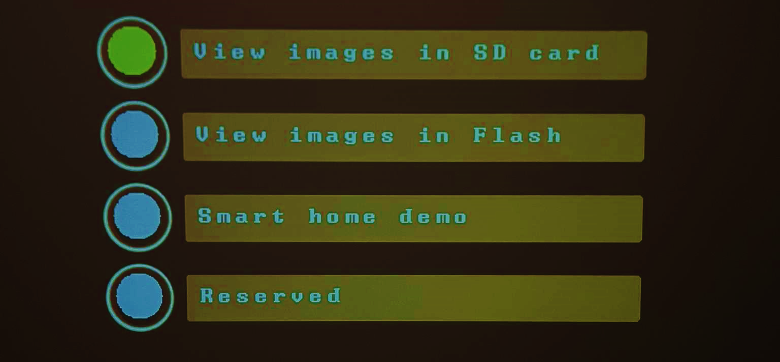 |
| A description for each menu can be found in Section 2.3.1. | ||
| Change menu selection | Quick button (SW2) press to cycle through all the menus. Selected menu button changes to yellow to confirm menu selection change. | There are 4 main menu options: View images in SD card, View images in Flash, Smart home demo, and Reserved. Menu selections are explained below. |
| Confirm menu selection | Long (>2 sec) button (SW2) press to confirm the menu selection. | The user action results in a button press animation to confirm selection. |