JAJS177F November 2003 – February 2020 TPS2490 , TPS2491
PRODUCTION DATA.
- 1 特長
- 2 アプリケーション
- 3 概要
- 4 改訂履歴
- 5 Pin Configuration and Functions
- 6 Specifications
- 7 Detailed Description
- 8 Application and Implementation
- 9 Power Supply Recommendations
- 10Layout
- 11デバイスおよびドキュメントのサポート
- 12メカニカル、パッケージ、および注文情報
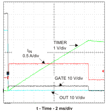
7.4.4 Response to a Hard Output Short (Figure 15 and Figure 16)
Figure 15 shows the short circuit response over the full time-out period. The period begins when the output voltage falls and ends when Q1 is turned off. Q1 current is actively controlled by the constant power engine and gate amplifier circuit while the TIMER pin charges CT to the 4-V threshold causing Q1 to be turned off. The TPS2490 latches off after the threshold is reached until either the input voltage drops below the UVLO threshold or EN cycles through the false (low) state. The TPS2491 goes through a timing sequence before attempting a restart.
 Figure 15. Current Limit Overview
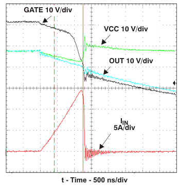
 The TPS249x responds rapidly to the short circuit as seen in Figure 16. The falling OUT voltage is the result of Q1 and CO currents through the short’s impedance at this time scale. The internal GATE clamp causes the GATE voltage to follow the output voltage down and subsequently limits the negative VGS to 1 V to 2 V. The rapidly rising fault current overdrives the GATE amplifier causing it to overshoot and rapidly turn Q1 off by sinking current to ground. Q1 slowly turns back on as the GATE amplifier recovers; Q1 then settles to an equilibrium operating point determined by the power limiting circuit.
 Figure 16. Current Limit Onset
 Minimal input voltage overshoot appears in Figure 16 because a local 100-µF bypass capacitor and very short input leads were used. The input voltage would overshoot as the input current abruptly drops in a typical application due to the stored energy in the input distribution’s inductance. The exact waveforms seen in an application depend upon many factors including parasitics of the voltage distribution, circuit layout, and the short itself.