JAJSE93B March   2016  – November 2017 LM5161

PRODUCTION DATA.  

  1. 特長
  2. アプリケーション
  3. 概要
    1.     Device Images
      1.      代表的な降圧アプリケーション回路
      2.      代表的なFly-Buckアプリケーション回路
  4. 改訂履歴
  5. Pin Configuration and Functions
    1.     Pin Functions
  6. Specifications
    1. 6.1 Absolute Maximum Ratings
    2. 6.2 ESD Ratings
    3. 6.3 Recommended Operating Conditions
    4. 6.4 Thermal Information
    5. 6.5 Electrical Characteristics
    6. 6.6 Switching Characteristics
    7. 6.7 Typical Characteristics
  7. Detailed Description
    1. 7.1 Overview
    2. 7.2 Functional Block Diagram
    3. 7.3 Feature Description
      1. 7.3.1  Control Circuit
      2. 7.3.2  VCC Regulator
      3. 7.3.3  Regulation Comparator
      4. 7.3.4  Soft-Start
      5. 7.3.5  Error Transconductance (GM) Amplifier
      6. 7.3.6  On-Time Generator
      7. 7.3.7  Current Limit
      8. 7.3.8  N-Channel Buck Switch and Driver
      9. 7.3.9  Synchronous Rectifier
      10. 7.3.10 Enable / Undervoltage Lockout (EN/UVLO)
      11. 7.3.11 Thermal Protection
    4. 7.4 Device Functional Modes
      1. 7.4.1 Forced Pulse Width Modulation (FPWM) Mode
      2. 7.4.2 Undervoltage Detector
  8. Applications and Implementation
    1. 8.1 Application Information
    2. 8.2 Typical Applications
      1. 8.2.1 LM5161 Synchronous Buck (15-V to 95-V Input, 12-V Output, 1-A Load)
        1. 8.2.1.1 Design Requirements
        2. 8.2.1.2 Detailed Design Procedure
          1. 8.2.1.2.1  Custom Design With WEBENCH® Tools
          2. 8.2.1.2.2  Output Resistor Divider Selection
          3. 8.2.1.2.3  Frequency Selection
          4. 8.2.1.2.4  Inductor Selection
          5. 8.2.1.2.5  Output Capacitor Selection
          6. 8.2.1.2.6  Series Ripple Resistor - RESR (FPWM = 1)
          7. 8.2.1.2.7  VCC and Bootstrap Capacitor
          8. 8.2.1.2.8  Input Capacitor Selection
          9. 8.2.1.2.9  Soft-Start Capacitor Selection
          10. 8.2.1.2.10 EN/UVLO Resistor Selection
        3. 8.2.1.3 Application Curves
      2. 8.2.2 LM5161 Isolated Fly-Buck (36-V to 72-V Input, 12-V, 12-W Isolated Output)
        1. 8.2.2.1 LM5161 Fly-Buck Design Requirements
        2. 8.2.2.2 Detailed Design Procedure
          1. 8.2.2.2.1 Selection of VOUT and Turns Ratio
          2. 8.2.2.2.2 Secondary Rectifier Diode
          3. 8.2.2.2.3 External Ripple Circuit
          4. 8.2.2.2.4 Output Capacitor (CVISO)
        3. 8.2.2.3 Application Curves
      3. 8.2.3 Ripple Configuration
    3. 8.3 Do's and Don'ts
  9. Power Supply Recommendations
  10. 10Layout
    1. 10.1 Layout Guidelines
    2. 10.2 Layout Example
  11. 11デバイスおよびドキュメントのサポート
    1. 11.1 WEBENCH®ツールによるカスタム設計
    2. 11.2 関連資料
    3. 11.3 ドキュメントの更新通知を受け取る方法
    4. 11.4 コミュニティ・リソース
    5. 11.5 商標
    6. 11.6 静電気放電に関する注意事項
    7. 11.7 Glossary
  12. 12メカニカル、パッケージ、および注文情報

Typical Characteristics

At TA = 25°C and applicable to LM5161 unless otherwise noted.
LM5161 eff_3v3_fpwm0_SNVU504.gif
VOUT = 3.3 V RON = 110 kΩ
FPWM = 0
Figure 1. Efficiency at 300 kHz
LM5161 EFF_12VOUT_fpwm1_ext_vs_intVcc_SNVU504.gif
VOUT = 12 V RON = 402 kΩ
FPWM = 0 L = 100 µH
Figure 3. Efficiency at 300 kHz
LM5161 LineReg_extVcc_fpwm1_SNVU504.gif
VOUT = 12 V RON = 300 kΩ
FPWM = 1 L = 100 µH
Figure 5. Line Regulation
LM5161 Icc_vcc_SNVU504.gif
VIN = 48 V
Figure 7. VCC vs ICC
LM5161 cl_fb_SNVU504.gif
Figure 9. TOFF (ILIM) vs VFB
LM5161 ONTIME_12V_5V_SNVU504.gif
Figure 11. TON vs VIN
LM5161 SD_VIN_SNVU504.gif
Figure 13. Shutdown Current vs VIN
LM5161 VRON_VIN_R1_SNVU504.gif
Figure 15. Voltage at RON pin vs Input Voltage
LM5161 Ref_TEMP_SNVU504.gif
VIN = 48 V
Figure 17. Reference Voltage vs Temperature
LM5161 SD_TEMP_SNVU504.gif
VIN = 48 V
Figure 19. Input Shutdown Current vs Temperature
LM5161 CL_TEMP_SNVU504.gif
VIN = 48 V
Figure 21. Current Limit vs Temperature
LM5161 FPWM_TEMP_SNVU504.gif
VIN = 48 V
Figure 23. FPWM Threshold vs Temperature
LM5161 Eff_5V_300k_CCMvsDCM_SNVU504.gif
VOUT = 5 V RON = 169 kΩ
L=47 µH
Figure 2. Efficiency at 300 kHz
LM5161 eff_VIN_12Vout_fpwm1_SNVU504.gif
VOUT = 12 V RON = 402 kΩ
FPWM = 1 L = 100 µH
Figure 4. Efficiency at 300 kHz
LM5161 Vcc_VIN_SNVU504.gif
Figure 6. VCC vs VIN
LM5161 ICCvsExtVCC_SNVU504.gif
IOUT = 1 A FPWM = 0
Figure 8. ICC vs External VCC
LM5161 OnTime_VIN_SNVU504.gif
Figure 10. TON vs VIN
LM5161 Fsw_vs_VIN_R1_SNVU504.gif
VOUT = 12 V
Figure 12. FSW vs VIN
LM5161 Operating_VIN_SNVU504.gif
VFB = 3 V
Figure 14. IIN vs VIN (Operating, Non Switching)
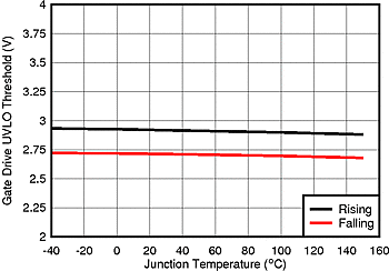
LM5161 GD_UVLO_TEMP_SNVU504.gif
VIN = 48 V
Figure 16. Gate Drive UVLO vs Temperature
LM5161 OP_TEMP_SNVU504.gif
VIN = 48 V
Figure 18. Input Operating Current vs Temperature
LM5161 Vcc_UVLO_TEMP_SNVU504.gif
VIN = 48 V
Figure 20. VCC UVLO vs Temperature
LM5161 sinkCL_TEMP_SNVU504.gif
VIN = 48 V
Figure 22. Sink Current Limit vs Temperature
LM5161 RDSON_TEMP_SNVU504.gif
ISW = 500 mA VIN = 48 V
Figure 24. Switch Resistance vs Temperature