10.2 Typical Performance Curves
Using circuit shown in Figure 23, TA = 25°C, unless otherwise specified.
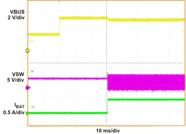
| VBUS = 0-5V, |
Iin_limit = 500mA, |
Voreg = 4.2V |
| VBAT = 3.5V, |
ICHG = 550mA, |
32S mode |
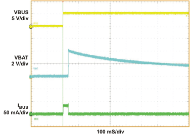
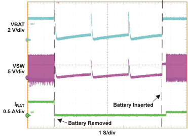
| VBUS = 5 V |
No Battery Connected |
|
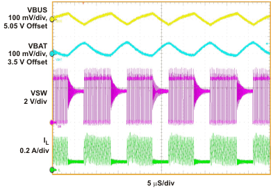
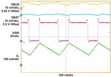
| VBUS = 5.05 V, |
VBAT = 3.5V, |
IBUS = 42 mA |
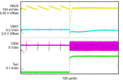
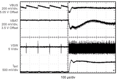
| VBUS = 5.05 V, |
VBAT = 3.5V, |
IBUS = 0-217 mA |
| VBUS = 5 V |
VBAT = 3.4 V |
Iin_limit = 500 mA |
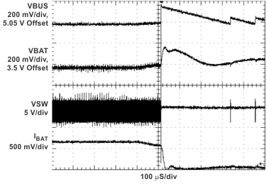
| VBUS = 5.05 V, |
VBAT = 3.5V, |
IBUS = 217 mA |
| VBUS = 5.05, |
VBAT = 3.5V, |
IBUS = 0-360 mA |
| VBUS = 5.05, |
VBAT = 3.5V, |
IBUS = 360-0 mA |


