JAJSKF6C November 2020 – December 2021 TPS2661
PRODUCTION DATA
- 1 特長
- 2 アプリケーション
- 3 概要
- 4 Revision History
- 5 Device Comparison Table
- 6 Pin Configuration and Functions
- 7 Specifications
-
8 Detailed Description
- 8.1 Overview
- 8.2 Functional Block Diagram
- 8.3
Feature Description
- 8.3.1 Overload Protection and Fast-Trip
- 8.3.2 Reverse Current Blocking for Unipolar Current Inputs TPS26610, TPS26611 and TPS26612 (4–20 mA, 0–20 mA)
- 8.3.3 OUTPUT and INPUT Cutoff During Overvoltage, Undervoltage Due to Miswiring
- 8.3.4 External Power Supply (±Vs)
- 8.3.5 Loop Testing Without ±Vs Supply (Loop Power Mode in TPS26610, TPS26613 Only)
- 8.3.6 Enable Control With TPS26611, TPS26612, and TPS26614
- 8.3.7 Signal Good Indicator (SGOOD)
- 8.4 Device Functional Modes
-
9 Application and Implementation
- 9.1 Application Information
- 9.2 Typical Application: Analog Input Protection for Current Inputs with TPS26610
- 9.3 Typical Application: Analog Input Protection for Multiplexed Current and Voltage Inputs with TPS26611
- 9.4 System Examples
- 10Power Supply Recommendations
- 11Layout
- 12Device and Documentation Support
- 13Mechanical, Packaging, and Orderable Information
8.3.5.1 Supply Sensing With VSNS for Loop Power Mode With TPS26610 and TPS26613
For the TPS26610 and TPS26613 devices, the set-point for transition to loop power mode can be set by connecting resistors (R1, R2) from +Vs pin to VSNS pin and GND pin as shown in Figure 8-18. The set-point can be calculated as per Table 8-2. TI recommends to use resistors R1 and R2 for supply sensing when voltage across burden resistor (ILOOP × RBurden) is more than 1.8 V. If VSNS is left open or floating, the device transitions to loop power mode when +Vs is less than 1.8 V.
Table 8-2 Supply Sensing With VSNS for
Loop Power Mode
| Device Power Mode | +Vs Voltage |
|---|---|
| ±Vs supplies | +Vs ≥ V(SNSR) × (R1 + R2) / R2(1) |
| Loop power | +Vs ≤ V(SNSF) × (R1 + R2) / R2(1)(2) |
(1) Use (R1 + R2) ≤ (+Vs) / (45 μA).
For V(SNSR) and V(SNSF) values, see the Electrical Characteristics.
(2) Keep V(SNSF) × (R1 +
R2) / R2 > (ILOOP × RBurden)
Figure 8-18 Supply Sensing With
VSNS

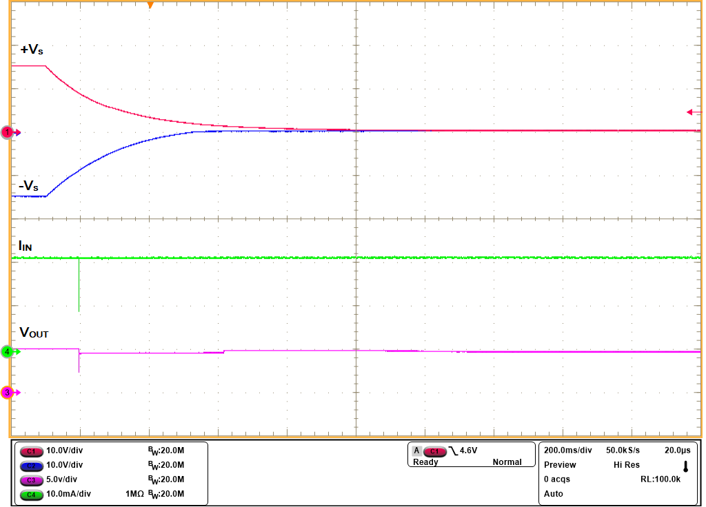
| +Vs = 15 V, –Vs = –15 V, ROUT = 250 Ω, MODE = GND |

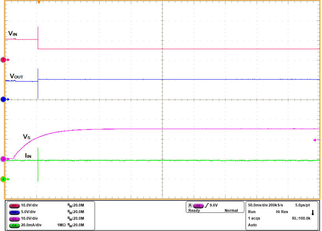
| +Vs = 15 V, –Vs = –15 V, ROUT = 250 Ω, MODE = GND |