JAJSLU5B December   2021  – August 2024 TPS63901

PRODUCTION DATA  

  1.   1
  2. 特長
  3. アプリケーション
  4. 概要
  5. Pin Configuration and Functions
  6. Specifications
    1. 5.1 Absolute Maximum Ratings
    2. 5.2 ESD Ratings
    3. 5.3 Recommended Operating Conditions
    4. 5.4 Thermal Information
    5. 5.5 Electrical Characteristics
    6. 5.6 Typical Characteristics
  7. Detailed Description
    1. 6.1 Overview
    2. 6.2 Functional Block Diagram
    3. 6.3 Feature Description
      1. 6.3.1 Trapezoidal Current Control
      2. 6.3.2 Device Enable and Disable
      3. 6.3.3 Soft Start
      4. 6.3.4 Input Current Limit
      5. 6.3.5 Dynamic Voltage Scaling
      6. 6.3.6 Device Configuration (Resistor-to-Digital Interface)
      7. 6.3.7 SEL Pin
      8. 6.3.8 Short-Circuit Protection
        1. 6.3.8.1 Current Limit Setting = 'Unlimited'
        2. 6.3.8.2 Current Limit Setting = 1 mA to 100 mA
      9. 6.3.9 Thermal Shutdown
    4. 6.4 Device Functional Modes
  8. Application and Implementation
    1. 7.1 Application Information
    2. 7.2 Typical Application
      1. 7.2.1 Design Requirements
      2. 7.2.2 Detailed Design Procedure
        1. 7.2.2.1 Inductor Selection
        2. 7.2.2.2 Output Capacitor Selection
        3. 7.2.2.3 Input Capacitor Selection
        4. 7.2.2.4 Setting The Output Voltage
      3. 7.2.3 Application Curves
  9. Power Supply Recommendations
  10. Layout
    1. 9.1 Layout Guidelines
    2. 9.2 Layout Example
  11. 10Device and Documentation Support
    1. 10.1 Device Support
      1. 10.1.1 Third-Party Products Disclaimer
    2. 10.2 Documentation Support
      1. 10.2.1 Related Documentation
    3. 10.3 ドキュメントの更新通知を受け取る方法
    4. 10.4 サポート・リソース
    5. 10.5 Trademarks
    6. 10.6 静電気放電に関する注意事項
    7. 10.7 用語集
  12. 11Revision History
  13. 12Mechanical, Packaging, and Orderable Information

Application Curves

Table 7-5 Components for Application Characteristic Curves for VOUT = 3.3 V
Reference(1)Description(2)Part NumberManufacturer
U1400-mA ultra low IQ buck-boost converter (1.5 mm × 1.15 mm)TPS63901YCJTexas Instruments
L12.2 µH, 2.5 mm × 2 mm 3.3 A, 82 mΩDFE252012F-2R2MMurata
C110 µF, 0603, ceramic capacitor, ±20%, 6.3 VGRM188R60J106ME47Murata
C222 µF, 0603, ceramic capacitor, ±20%, 6.3 VGRM187R60J226ME15Murata
CFG136.5 kΩ, 0603 resistor, 1%, 100 mWStandardStandard
CFG20 Ω, 0603 resistor, 1%, 100 mWStandardStandard
CFG30 Ω, 0603 resistor, 1%, 100 mWStandardStandard
For other output voltages, refer to Table 7-1 for resistor values.
TPS63901 Efficiency vs Output
                        Current
VO = 1.8 V TA = 25°C
Figure 7-2 Efficiency vs Output Current
TPS63901 Efficiency vs Output
                        Current
VO = 5.0 V TA = 25°C
Figure 7-4 Efficiency vs Output Current
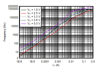
TPS63901 Typical Burst Switching
                        Frequency vs Output Current
VI = 3.3 VTA = 25°C
Figure 7-6 Typical Burst Switching Frequency vs Output Current
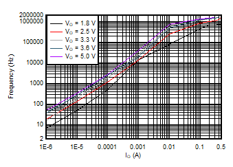
TPS63901 Typical Burst Switching
                        Frequency vs Output Current
VI = 5.2 VTA = 25°C
Figure 7-8 Typical Burst Switching Frequency vs Output Current
TPS63901 Output Voltage
                        Ripple
VI = 4.4 V TA = 25°C
Figure 7-10 Output Voltage Ripple
TPS63901 Load
                        Regulation
VI = 3.3 V TA = 25°C
Figure 7-12 Load Regulation
TPS63901 Switching Waveforms, Boost Operation
VI = 1.8 V, VO = 3.3 VNo load
Figure 7-14 Switching Waveforms, Boost Operation
TPS63901 Switching Waveforms, Buck Operation
VI = 4.0 V, VO = 3.3 VNo load
Figure 7-16 Switching Waveforms, Buck Operation
TPS63901 Line Transient, 400-mA
                        Load
VI = 2.5 V to 4.2 V, VO = 3.3 V Load = 400-mA resistive load
Figure 7-18 Line Transient, 400-mA Load
TPS63901 Load Transient, 300-mA
                        Step
VI = 3.3 V, VO = 3.3 V Load = 0 mA to 300 mA, tr/tf = 2 μs
Figure 7-20 Load Transient, 300-mA Step
TPS63901 Load Transient, 300-mA
                        Step
VI = 5.5 V, VO = 3.3 V Load = 0 mA to 300 mA, tr/tf = 2 μs
Figure 7-22 Load Transient, 300-mA Step
TPS63901 Start-Up Behavior from Rising Enable
VI = 3.3 V, VO = 3.3 V 100-mA resistive load
Figure 7-24 Start-Up Behavior from Rising Enable
TPS63901 Start-Up with 50-mA
                        ICL
VI = 3.3 V, VO = 3.3 V CI = 32 μF, CO = 300 μF
Figure 7-26 Start-Up with 50-mA ICL
TPS63901 Short Circuit
                        Behavior
VI = 3.3 V, VO = 3.3 V TA = 25°C
Figure 7-28 Short Circuit Behavior
TPS63901 DVS
                        Behavior at Light Load
VI = 3.3 V, VO(1) = 2.2 V, VO(2) = 3.6 V 0.1-mA resistive load
Figure 7-30 DVS Behavior at Light Load
TPS63901 Efficiency vs Output Current
VO = 3.3 V TA = 25°C
Figure 7-3 Efficiency vs Output Current
TPS63901 Typical Output Current
                        Capability vs Input Voltage
TA = 25°C
Figure 7-5 Typical Output Current Capability vs Input Voltage
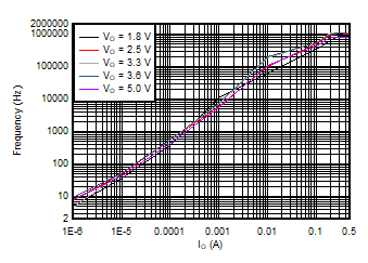
TPS63901 Typical Burst Switching
                        Frequency vs Output Current
VI = 2.0 VTA = 25°C
Figure 7-7 Typical Burst Switching Frequency vs Output Current
TPS63901 Output Voltage
                        Ripple
VI = 3.3 V TA = 25°C
Figure 7-9 Output Voltage Ripple
TPS63901 Output Voltage
                        Ripple
VI = 5.2 V TA = 25°C
Figure 7-11 Output Voltage Ripple
TPS63901 Line
                        Regulation
VI = 1.8 V to 5.0 V Load = 1 mA, TA = 25°C
Figure 7-13 Line Regulation
TPS63901 Switching Waveforms, Buck-Boost Operation
VI = 3.3 V, VO = 3.3 VNo load
Figure 7-15 Switching Waveforms, Buck-Boost Operation
TPS63901 Line Transient, 200-mA
                        Load
VI = 2.5 V to 4.2 V, VO = 3.3 V Load = 200-mA resistive load
Figure 7-17 Line Transient, 200-mA Load
TPS63901 Load Transient, 300-mA
                        Step
VI = 2.7 V, VO = 3.3 V Load = 0 mA to 300 mA, tr/tf = 2 μs
Figure 7-19 Load Transient, 300-mA Step
TPS63901 Load Transient, 300-mA Step
VI = 4.2 V, VO = 3.3 V Load = 0 mA to 300 mA, tr/tf = 2 μs
Figure 7-21 Load Transient, 300-mA Step
TPS63901 Start-Up Behavior from Rising
                        Enable
VI = 3.3 V, VO = 3.3 V 10-μA resistive load
Figure 7-23 Start-Up Behavior from Rising Enable
TPS63901 Start-Up with 100-mA
                        ICL
VI = 3.3 V, VO = 3.3 V CI = 32 μF, CO = 300 μF
Figure 7-25 Start-Up with 100-mA ICL
TPS63901 Short Circuit
                        Behavior
VI = 1.8 V, VO = 3.3 V TA = 25°C
Figure 7-27 Short Circuit Behavior
TPS63901 Short Circuit
                        Behavior
VI = 5.0 V, VO = 3.3 V TA = 25°C
Figure 7-29 Short Circuit Behavior
TPS63901 DVS
                        Behavior at High Load
VI = 3.3 V, VO(1) = 2.2 V, VO(2) = 3.6 V 400-mA resistive load
Figure 7-31 DVS Behavior at High Load