JAJSRX9C January 2012 – November 2023 TPS40170-Q1
PRODUCTION DATA
- 1
- 1 特長
- 2 アプリケーション
- 3 概要
- 4 Pin Configuration and Functions
- 5 Specifications
-
6 Detailed Description
- 6.1 Overview
- 6.2 Functional Block Diagram
- 6.3
Feature Description
- 6.3.1 LDO Linear Regulators and Enable
- 6.3.2 Input Undervoltage Lockout (UVLO)
- 6.3.3 Equations for Programming the Input UVLO
- 6.3.4 Overcurrent Protection and Short-Circuit Protection (OCP and SCP)
- 6.3.5 Oscillator and Voltage Feed-Forward
- 6.3.6 Feed-Forward Oscillator Timing Diagram
- 6.3.7 Soft-Start and Fault-Logic
- 6.3.8 Overtemperature Fault
- 6.3.9 Tracking
- 6.3.10 Adaptive Drivers
- 6.3.11 Start-Up Into Pre-Biased Output
- 6.3.12 31
- 6.3.13 Power Good (PGOOD)
- 6.3.14 PGND and AGND
- 6.3.15 Bootstrap Capacitor
- 6.3.16 Bypass and Filtering
- 6.4 Device Functional Modes
-
7 Application and Implementation
- 7.1 Application Information
- 7.2
Typical Application
- 7.2.1 Design Requirements
- 7.2.2
Detailed Design Procedure
- 7.2.2.1 Select A Switching Frequency
- 7.2.2.2 Inductor Selection (L1)
- 7.2.2.3 Output Capacitor Selection (C9)
- 7.2.2.4 Peak Current Rating of Inductor
- 7.2.2.5 Input Capacitor Selection (C1, C6)
- 7.2.2.6 MOSFET Switch Selection (Q1, Q2)
- 7.2.2.7 Timing Resistor (R7)
- 7.2.2.8 UVLO Programming Resistors (R2, R6)
- 7.2.2.9 Bootstrap Capacitor (C7)
- 7.2.2.10 VIN Bypass Capacitor (C18)
- 7.2.2.11 VBP Bypass Capacitor (C19)
- 7.2.2.12 SS Timing Capacitor (C15)
- 7.2.2.13 ILIM Resistor (R19, C17)
- 7.2.2.14 SCP Multiplier Selection (R5)
- 7.2.2.15 Feedback Divider (R10, R11)
- 7.2.2.16 Compensation: (R4, R13, C13, C14, C21)
- 7.2.3 Application Curves
- 7.3 Power Supply Recommendations
- 7.4 Layout
- 8 Device and Documentation Support
- 9 Revision History
- 10Mechanical, Packaging, and Orderable Information
3 概要
TPS40170-Q1 デバイスは、4.5V~60V の入力電圧で動作するフル機能の同期整流 PWM 降圧コントローラで、電力密度が高く信頼性の高い DC/DC コンバータ・アプリケーションに最適化されています。このコントローラは、入力電圧フィードフォワード補償による電圧モード制御を実装し、入力電圧の変化に対する瞬時の応答を可能にします。スイッチング周波数は 100kHz~600kHz の範囲で設定可能です。
TPS40170-Q1 デバイスは、プログラム可能な UVLO、ローサイド FET の検出によるプログラム可能な過電流保護 (OCP)、ハイサイド FET の検出による選択可能な短絡保護 (SCP)、サーマル・シャットダウンなど、一連のシステム保護および監視機能を備えています。ENABLE ピンにより、低電流 (代表値 1μA) モードでシステム・シャットダウンが可能です。このコントローラは、プリバイアス出力をサポートし、オープン・ドレインの PGOOD 信号を供給するほか、閉ループのソフトスタート、出力電圧トラッキング、適合型デッドタイム制御を備えています。
TPS40170-Q1 デバイスは、精度 1% 内の正確な出力電圧レギュレーショを実現します。さらに、このコントローラは 1 つのコントローラがプライマリ・コントローラとして動作し、他のダウンストリーム・コントローラが 1 次側に同相、または 180° 位相不一致に同期しているセカンダリ・コントローラとして動作している新しい双方向同期方式を実装しています。セカンダリ・コントローラは、フリーランニング・スイッチング周波数の ±30% 以内で外部クロックと同期できます。
新製品 (LM5145-Q1 および LM5146-Q1) には、BOM コストの削減、効率の向上、ソリューション・サイズの小型化など、多くの特長があります。
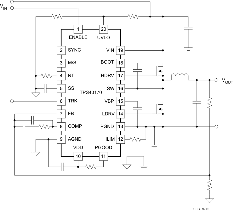
 概略回路図
概略回路図