JAJU787B April 2016 – May 2019 TPS2828 , TPS3828
5.3 Hybrid RF/PLC Test Results
This section shows the Hybrid RF/PLC test results to verify simultaneous transmissions and RF-to-PLC repeater functionality.
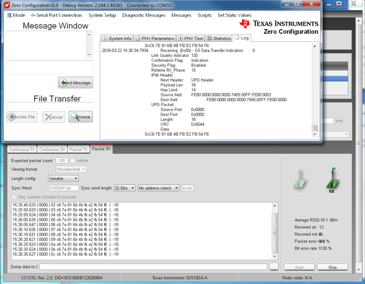
Figure 26 shows the simultaneous transmission test results with a 3-node setup. The Hybrid RF/PLC node starts to send 10B packets with intervals of 5 seconds to both RF and PLC nodes once PLC completely joins the process. The zero-configuration GUI on the PLC only node shows 10B packet reception (G3 Data Transfer.Indication) in the log window (top of Figure 26), and at the same time the RF only node receives the same packet (10B packet with RF sub-header information).

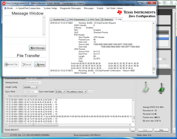
Figure 27 shows test results for PLC-to-RF repeater functionality. For the test, the PLC node sent a 50B UDP/IPv6 packet, meaning that the total packet size is 98B (50B payload + 40B IPv6 header + 8B UDP header). The zero-configuration GUI shows the packet transmission (G3 Data Transfer.Request) in the GUI. As a result, the Hybrid RF/PLC node forwarded the received PLC data to the RF link. Finally, the RF node shows the packet reception on the Packet RX window at the timestamp of 15:32:38.905. Note that, for this testing, the packet size sent by the PLC should be limited up to 70B because of the size limitation by the pre-programmed RF software. The RX packet size can be increased by flashing a new RF RX example binary with the increased maximum RX packet size.

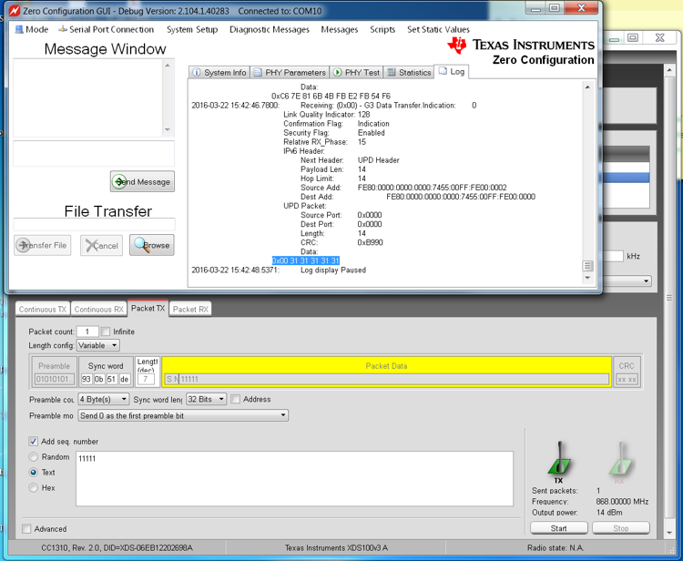
Figure 28 shows test results of the RF-to-PLC repeater. For the test, the RF node sent a 5B text message.
Once the 5B packet is received at the Hybrid RF/PLC node, the node passes the received data to the PLC link. The zero-configuration GUI shows the packet reception (in forms of G3 Data Transfer Indication) in the zero-configuration GUI (top in Figure 28). The received packet at PLC includes 6B of information (5B message + 1B sub-header inserted by the RF transmitter).
