JAJU848 April 2022 TPSI3050 , TPSI3050-Q1 , TPSI3052 , TPSI3052-Q1
3.3 Test Results
Figure 3-2 shows when the load current (ILOAD) is greater or equal to 2 A and the design implements a delay of at least 100 ms before disconnecting the load. From the scope capture taken, it can be observed that the delay is larger than 100 ms. This is because the negative swing threshold from the AND gate can vary from 0.9 V to 2.2 V. The max value of 2.2 V was chosen for the calculation to ensure that the delay is greater or equal to 100 ms.
- VDDP is the power supply for primary side.
- USER_INPUT is the input provided by the user when desired to connect the load.
- EN is the enable input to TPSI3050-Q1.
- ILOAD is the current through the load.
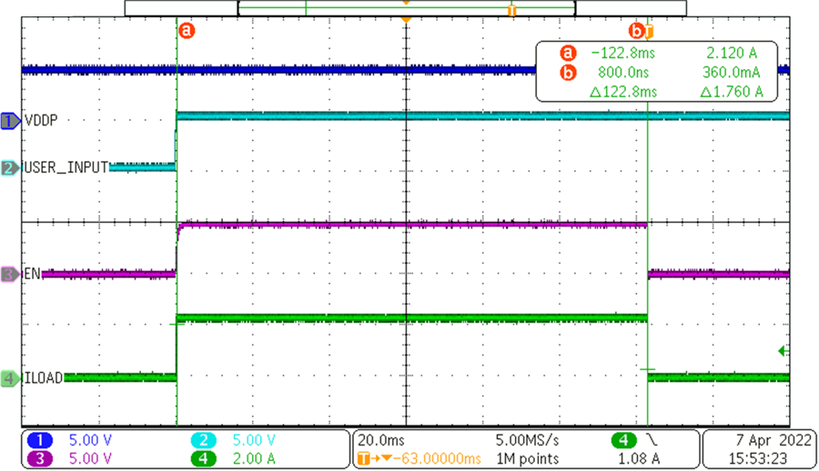 Figure 3-2 Scope Capture for 100-ms Delay
Load Disconnect
Figure 3-2 Scope Capture for 100-ms Delay
Load DisconnectFigure 3-3 shows the behavior of the circuit when a current greater than 5 A is detected. The current load increases above 5 A and the overcurrent protection disconnects the load with a minimal propagation delay of 6.3 µs.
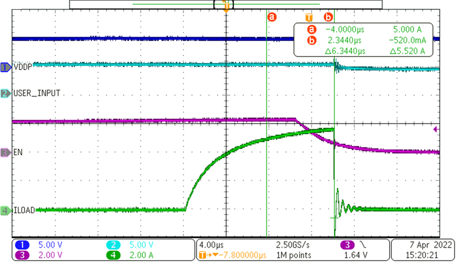 Figure 3-3 Scope Capture for Immediate
Load Disconnect
Figure 3-3 Scope Capture for Immediate
Load DisconnectFigure 3-4 shows the visual warning using a red LED when the temperature reaches 60 °C. Figure 3-5 and Figure 3-6 are thermal images taken for the two temperature protection levels. When temperature is between 60 °C to 90 °C a visual warning is provided via a red LED and when temperature is above 90 °C the load is disconnected.
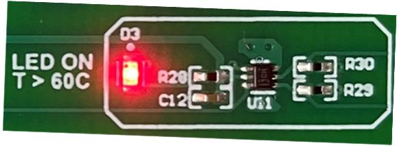 Figure 3-4 Red LED Warning Light
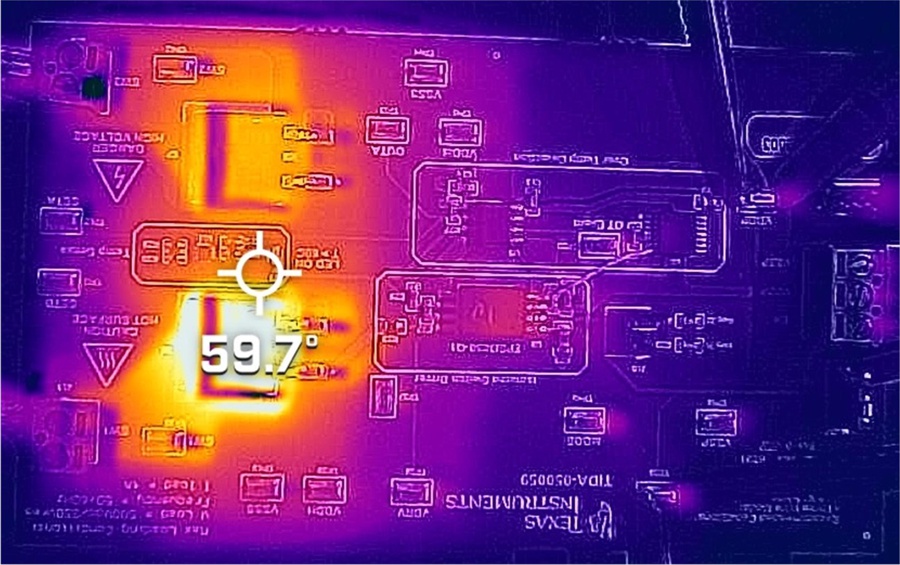 Figure 3-5 Thermal Image
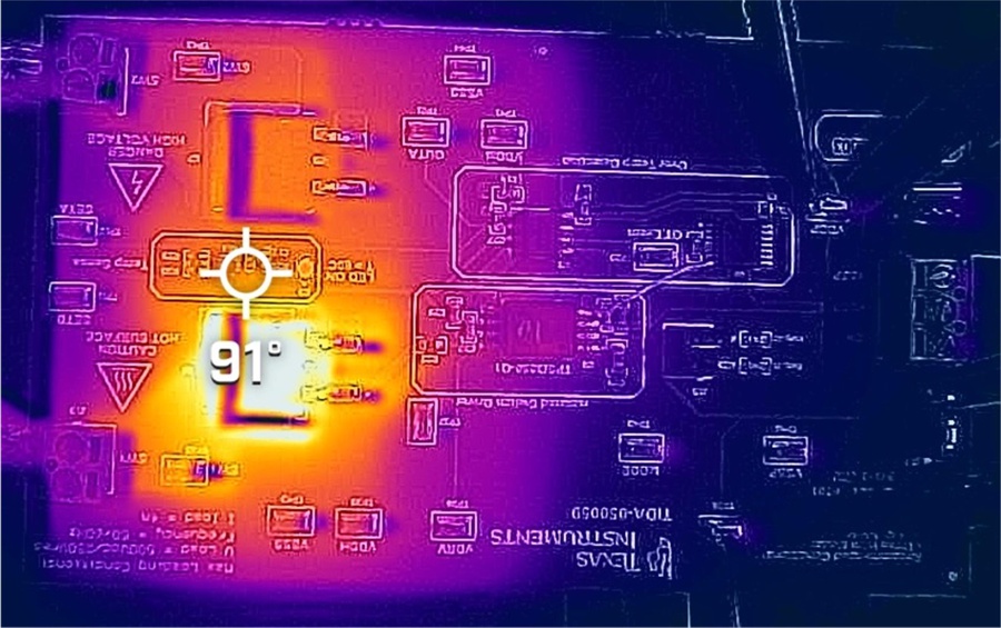 Figure 3-6 Thermal Image