SBAA449B October 2020 – October 2021 TMAG5110 , TMAG5110-Q1 , TMAG5111 , TMAG5111-Q1
3.2.2.3 Out-of-Plane Magnetic Field
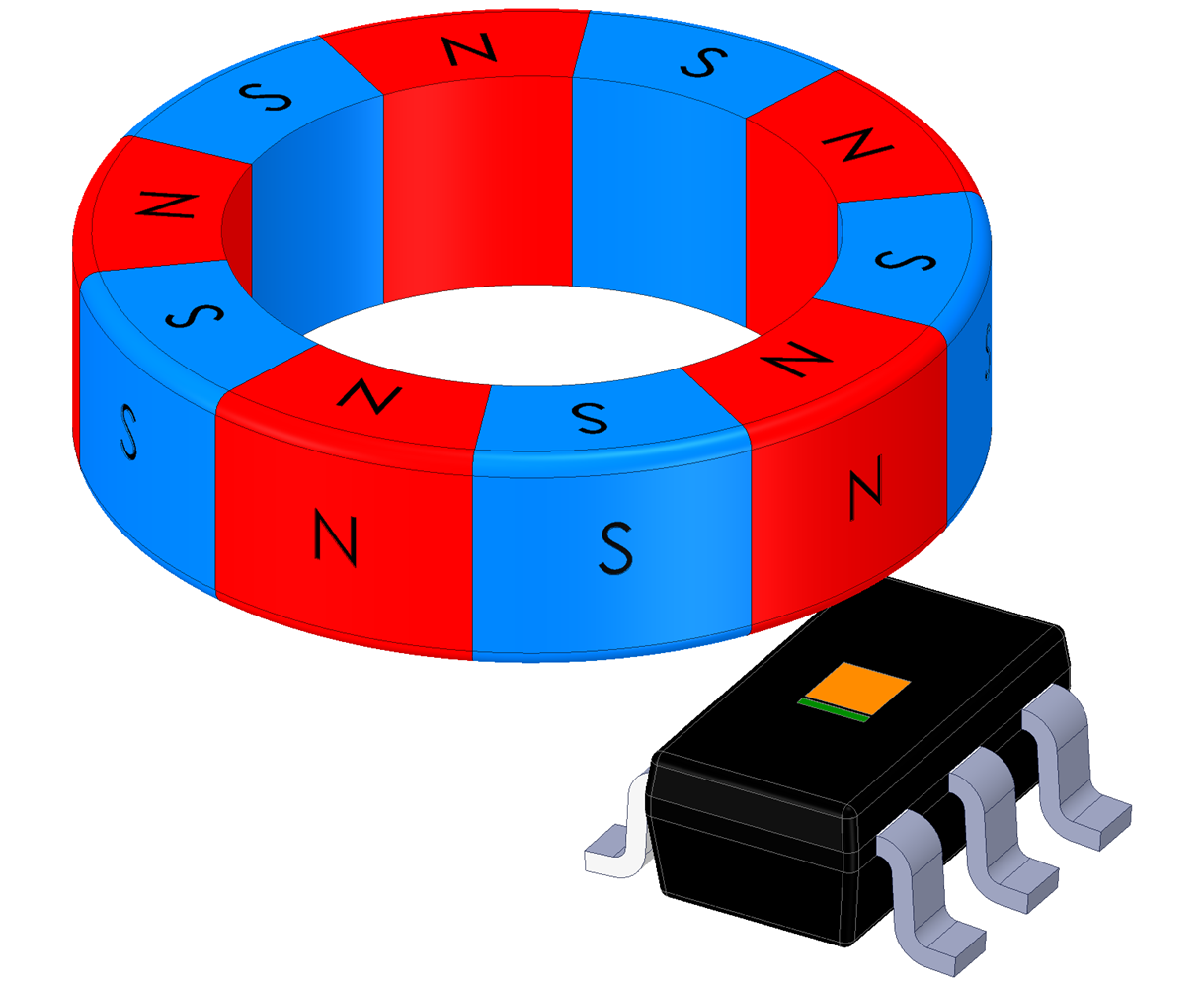
Out-of-Plane placement can be the easiest to configure mechanically. There are also measurable magnetic field components in all three directions. This gives the greatest flexibility for tracking magnet rotation.
 Figure 3-22 Sensor Out-of-Plane
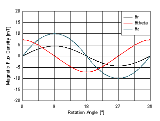
There is a significant issue here. The peak amplitudes of each component are so different from each other that there will be noticeable error. If we consider the components which are closest matched, Z and θ, an worst case error of about 1.83° is expected. This error becomes more significant with the sensor placed further from the magnet where the field is weaker.
 Figure 3-23 Out-of-Plane Magnetic Field Components
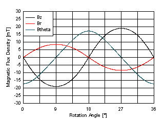
For comparison, observe the change to the peak amplitudes available with this type of magnet. In this case, the same material and dimensions are used, but the polarization is now directed outward from the face of the magnet. This type of polarization will allow for greater air gaps and pole counts for sensors in the out-of-plane alignment. However, they fail to produce adequate inputs when the device is in-plane with the magnet. These are often manufactured as custom magnets, and tend to be less commercially available .
 Figure 3-24 Face Polarized Magnet