SBAA615 December 2023 OPT4003-Q1
3 Light Source Ratios
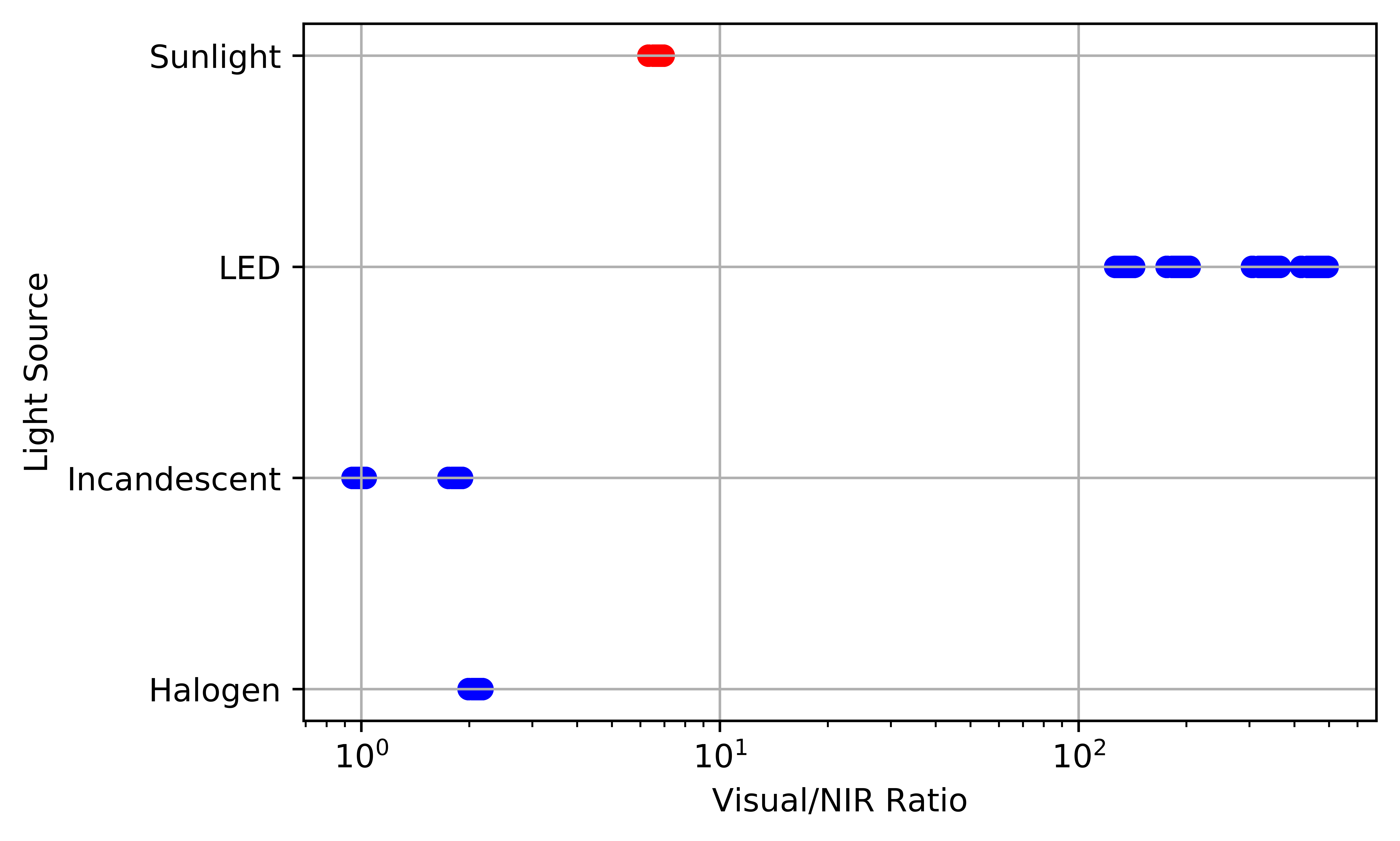
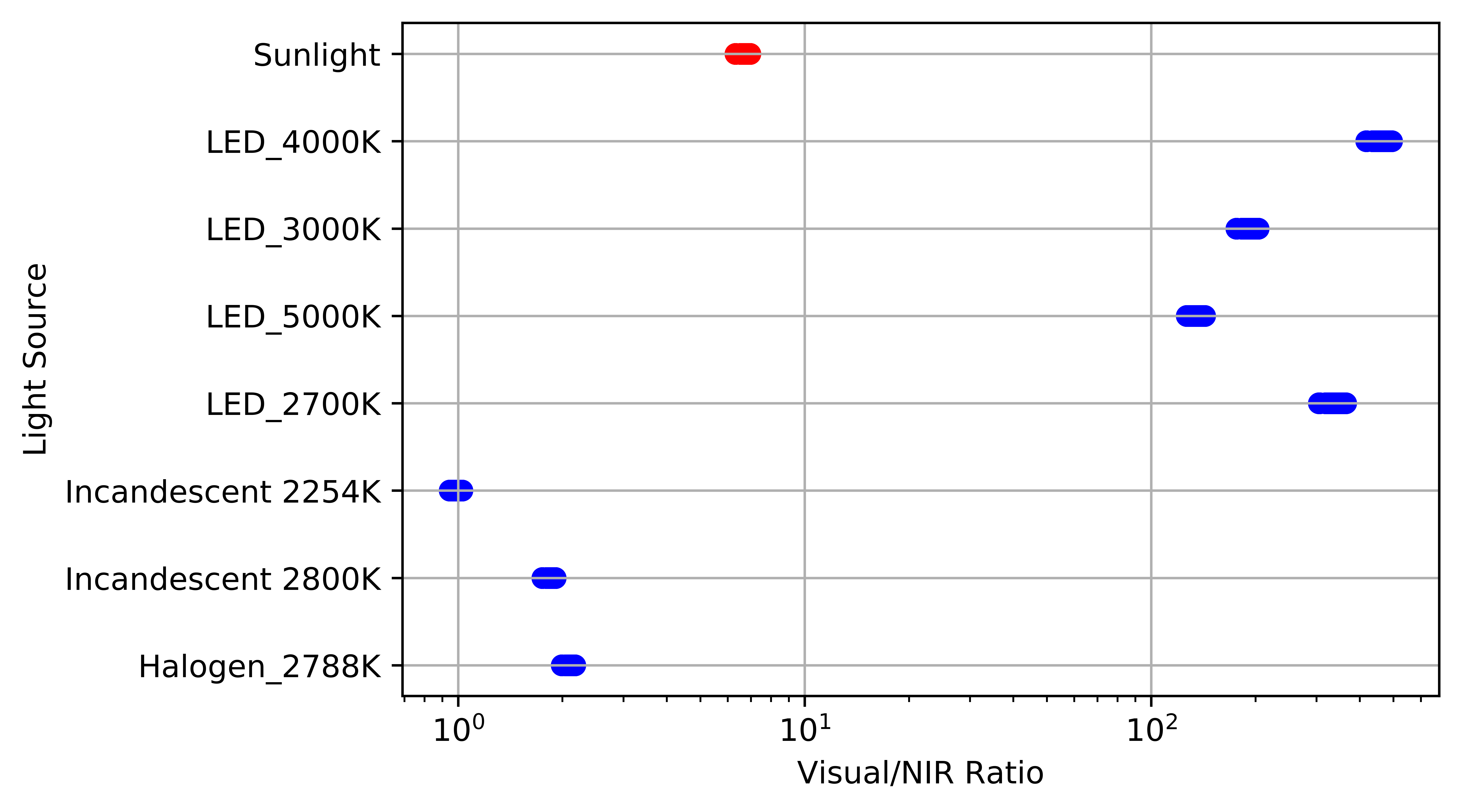
Figure 3-1 shows measured data from the OPT4003-Q1. The ratio of channel 0 codes to channel 1 codes is shown on the x-axis, with the light source categories listed on the y-axis. Each broader category includes different sources, which can be seen in Figure 3-2.
 Figure 3-1 Example of OPT4003-Q1 Light Source Ratios
 Figure 3-2 Expanded Example of OPT4003-Q1 Light Source Ratios
Measurements were taken with twenty-five OPT4003-Q1 devices to make sure of stability across units. The resulting light source ratios have clear and defined boundaries. For this data set, thresholds can be created to identify sunlight versus artificial sources.Table 4-2 lists the minimum and maximum ratios of all the indiviudual sources shown in Figure 3-2. The variation of ratios in each category is due to different color temperature sources being grouped together.
| Source | Minimum Measured Ratio | Maximum Measured Ratio |
|---|---|---|
| Sunlight | 6.31 | 6.97 |
| LED | 126.52 | 495.19 |
| Incandescent | 0.94 | 1.91 |
| Halogen | 1.99 | 2.18 |
Specific distinctions can be made by defining thresholds for each light source category, following the same pattern shown in the block of code below.
if (ratio > 2.2 and ratio < 11):
     source = sunlight
else:
     source = artificial