SBAU392A July 2022 – January 2023 AFE7950 , TRF1208
- TRF1208-AFE7950-EVM Evaluation Module User's Guide
- Trademarks
- 1EVM Overview
- 2Hardware Setup (TSW14J56 Used as an Example)
- 3Latte Overview
- 4TRF1208-AFE7950-EVM Automatic Configuration
- 5Status Check and Troubleshooting Guidelines
- 6TRF1208-AFE7950-EVM Manual Configuration
- 7Setup the TSW14J5x With the HSDC Pro
- 8Revision History
7.1 DAC Pattern Setup and Send
This section lists the steps to create and send a DAC pattern from the TSW14J5x board.
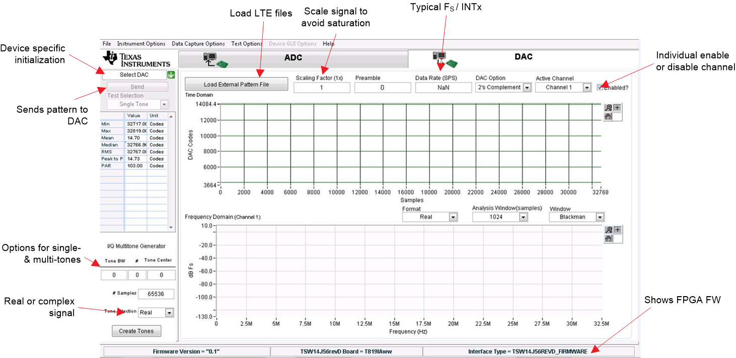
- Click on the HSDC Pro DAC tab. Figure 7-1 shows a brief description of the DAC tab.
 Figure 7-1 HSDC Pro DAC Tab Overview
 - A pictorial representation to create and send a sinusoid is shown in Figure 7-2.
 Figure 7-2 Setup a Sinusoid
 - How to create and send a sinusoid is outlined in the steps that follow:
- Select AFE79xx_2x2TX_44210 in the device-specific initialization option. Click Yes if prompted to download the firmware (FW). The default option is to run the board in the transceiver mode of operation, which enables simultaneous operation of the TX and the RX and FBRX. The FW used in transceiver mode has the letters XCVR in its name.
- Enter 491.52 M as the data rate and 0.9 for a scaling factor.
- Create a sinusoid by entering the frequency in the Tone Generator section of the HSDC Pro window.
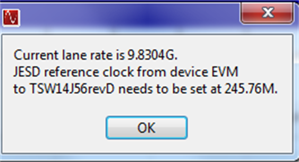
- Press Send to transmit the DAC pattern to the TRF1208-AFE7950-EVM. Figure 7-3 shows the resulting message with the lane rate and reference clock expected in the FPGA. Click OK.
 Figure 7-3 HSDC Pro Lane and Reference Clock Rate Pop-Up
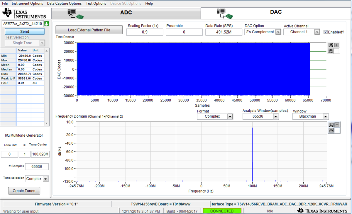
Figure 7-4 shows an example setup with a 100-MHz sinusoid.
 Figure 7-4 HSDC Pro CW
Alternately, a pattern file (for example, LTE) can be loaded and sent using the Load External Pattern File button.
The DAC setup is now complete.