SBAU428 September 2023 AFE7728D , AFE7768D , AFE7769 , AFE7769D , AFE7799 , AFE7920 , AFE7921 , AFE7952 , AFE7988 , AFE7989 , AFE8030 , AFE8092
4 Bring-Up Steps
The following section provides a step-by-step walkthrough of the reference design setup from a bring-up perspective, along with relevant screenshots of the process throughout.
Steps:
- First, power on the Agilex eSOM7 TI Carrier and then power on the TI AFE7769DEVM.
- Open Teraterm, click on "Serial", and click "OK".
- Click on Setup > Serial port, see
Figure 4-1.
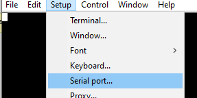 Figure 4-1 Opening Serial Port Window
in Teraterm
 - A new window will appear. Select the
COM port that the eSOM7 is connected to (not COM1). Change the speed to 115200 and
click "Close and New open", see Figure 4-2.
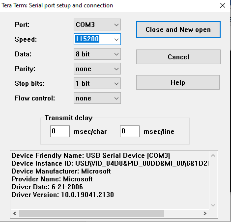 Figure 4-2 Serial Port Setup and
Connection
 - You should now see "agilex login:", if you do not see any text, hit enter and "agilex login" will appear.
- Type root and hit enter to login.
- Get the IP address of the Arm node
using the ifconfig command. If you do not see an "inet4" IP address under the
eth0 interface, use the command ifconfig eth0 192.168.0.1 netmask
255.255.255.0 to assign the 192.168.0.1 IP address to the eth0 interface,
see Figure 4-3.
 Figure 4-3 IP Address
Acquisition
 - On PowerShell, move your directory to the Hitek RF INTF release archive using the cd < Hitek RF INTF release archive path> command. In our setup, the command was cd C:\Users\a0503061\Documents\Hitek\AG_eSOM_AFE77XX_RF_INTF_DEMO_Release_v3_3_2023-04-2 5.
- Copy the software/arm_ag_/tools folder from the AG_eSOM_AFE77XX_RF_INTF_DEMO_Release_v3_3_2023-04-25 folder to the Arm node with the folder name as jesd_tools using the command scp -r software/arm_ag/tools/ root@192.168.0.1:~/jesd_tools/.
- Start the TI AFE77xxD Latte GUI
software and in the first dialog window titled "Latte Mode", make sure that
FPGA_Type is set to "None" and the "AFE EVM Card Detected" message appears. The
message "Couldn't Detect FPGA Reset FTDI. Reset FPGA manually." is expected. Then
press "Continue" button to open the main Latte GUI. For proper navigation to Latte
mode window, see Figure 4-4.
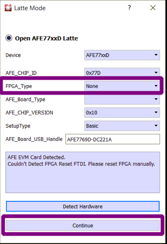 Figure 4-4 Launching the AFE77xxD
Latte GUI
 - After the
Latte software goes through its initialization steps, go to the AFE77xxD Params tab
by clicking on AFE77xxD-Params on the left panel of the software window. Figure 4-5 shows how to navigate to the respective tab on the software panel.
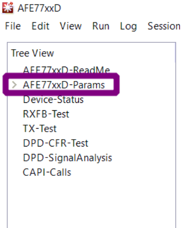 Figure 4-5 Navigating to
AFE77xxD-Params
 - In the "Load System Parameters" box,
click the "Browse" to search for the AFE77xxD_Config.json config file provided in
AG_eSOM_AFE77XX_RF_INTF_DEMO_Release_v3_3_2023-04-25\software\x64_64\utilities\AFE77xxDLatte_v0p4
and open it. For a view of the "AFE77xxD-Params" display and how to load the file,
see Figure 4-6 and Figure 4-7, respectively.
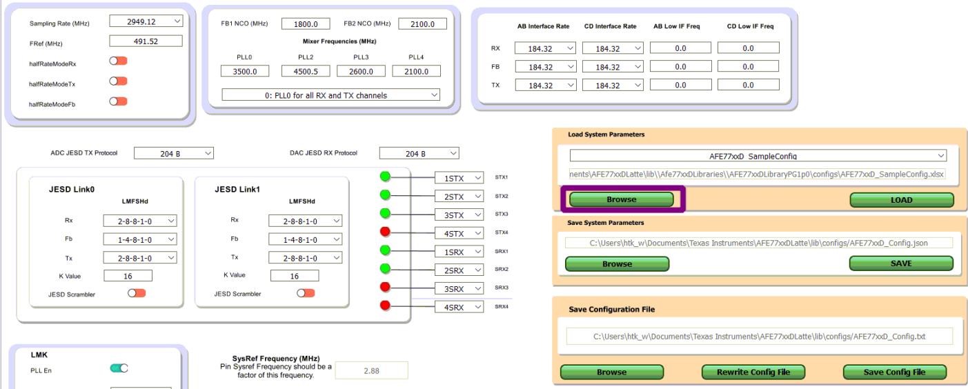 Figure 4-6 View of the
AFE77xxD-Params Display
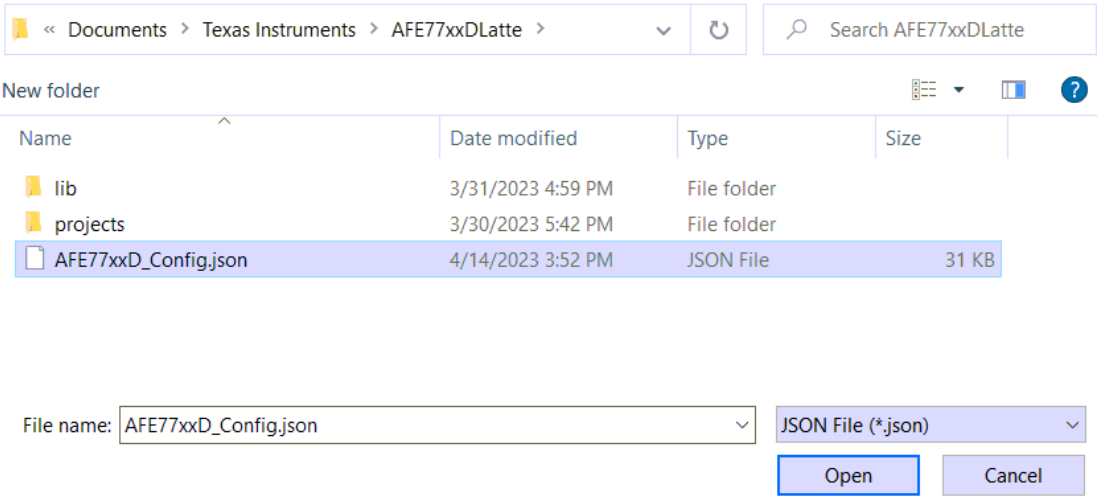 Figure 4-7 Loading the AFE77xxD
Configuration File Into Latte
 - After selecting the configuration file, please click the "LOAD" button to load the configuration into the GUI. The GUI should change to the required configuration to be able to perform JESD link up with the JESD IP in the Agilex FPGA.
- Open Quartus Prime Programmer and
click the "Auto Detect" button. For navigation to the respective function, see Figure 4-8. If this is the first time the eSOM7 is connected to the PC and the "Auto Detect"
button is grayed out, click on the "Hardware Setup..." button, select the "HTK
USBII" in the drop down next to "Currently selected hardware" and check that the
"Hardware frequency" is set to 24000000Hz.
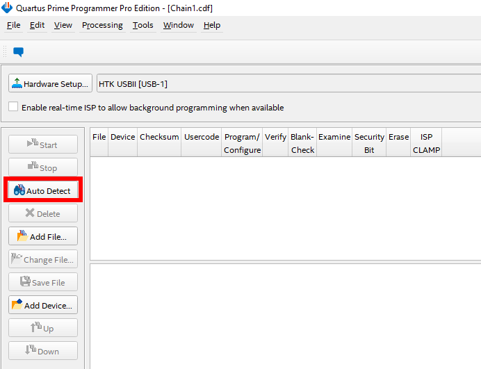 Figure 4-8 Auto Detect in Quartus
Prime Programmer
 - After
clicking "Auto Detect", a window will appear; select the AGFB027R24CR2 option and
click "OK". Figure 4-9 shows the typical view when selecting a device.
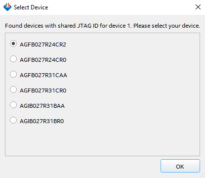 Figure 4-9 Device Selection
 - Select the only row under "File" and
then click on “Change File”. Select the FPGA image called
ag_esom_top_afe77xx_jesd204c_4t4r2f_fpga_first_hps_auto.sof that is
provided in the directory
AG_eSOM_AFE77XX_RF_INTF_DEMO_Release_v3_3_2023-04-25\snapshots\hardware\fpga\agfb027_r24c_asyXX\ag_esom_top_afe77xx_jesd204c_4t4r2f_fpga_first_20230421_012455,
where "XX" should match the "ASY-XX-00047" label on the eSOM7 board. There is an
extra copy of these files in a compressed .tar.gz folder. Figure 4-10 shows how to navigate to the proper functions.
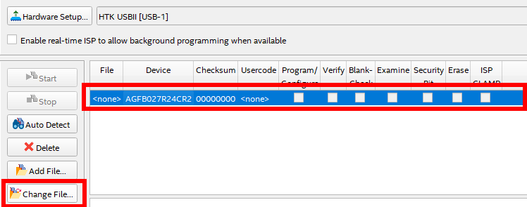 Figure 4-10 File Change
 - Next, check the box under
"Program/Configure", see Figure 4-11.
 Figure 4-11 Program/Configure
 - On the AFE77xxD GUI, the “Device
Bringup” button at the bottom of the AFE77xxD-Params page should be clicked to start
the configuration of the LMK04828 and AFE7769D chips. Figure 4-12 shows how to navigate to the respective button.
 Figure 4-12 Device Bringup,
AFE77xxD-Params
 - Once the “LMK Configured” message
appears in the TI AFE77xxD Latte software log window indicating completion of the
LMK04828 chip configuration, program the Agilex FPGA image by clicking the “Start”
button on Quartus Prime Programmer. Figure 4-13 and Figure 4-14 show a visual reference of the steps to program the device.
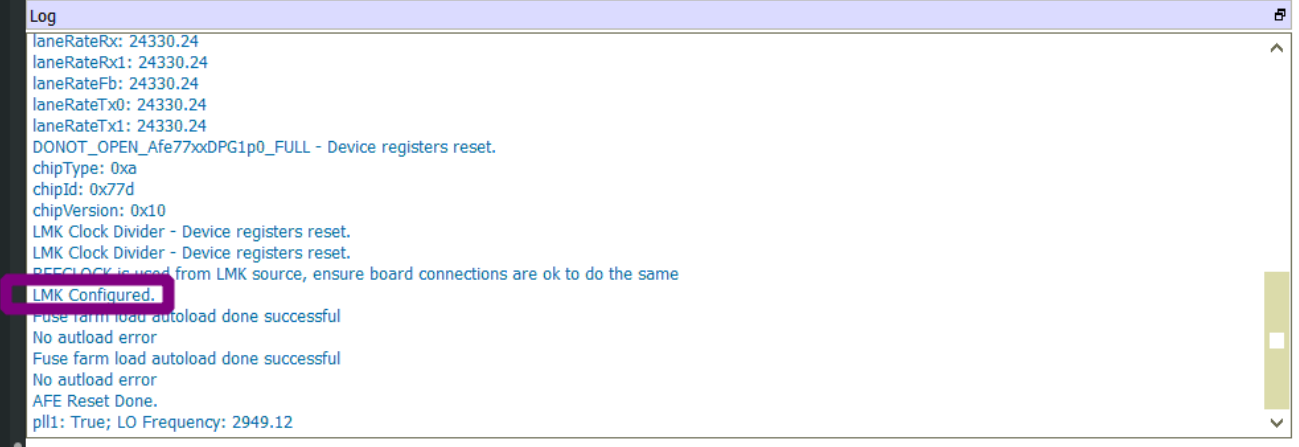 Figure 4-13 Confirmation of LMK
Configuration in the AFE77xxD Latte GUI
 Figure 4-14 Clicking the Start Button
to Program the Agilex FPGA
 - Wait for
Linux bootup of the Arm node to show up on the Teraterm console and login with the
root username. Then, use the command source
jesd_tools/init_term.sh to execute the init_term.sh script in the jesd_tools
folder, and run the run_jesd_init_afe77xx_jesd204c_4t4r2f_board.sh script on
the Arm node. Do not hit enter yet. Figure 4-15 shows an example block of code.
 Figure 4-15 Initializing JESD IP in
the Agilex FPGA
 - Wait until the AFE7769D configuration
completes in the TI AFE77xxD Latte software where it should report successful
JESD204C link up on the AFE7769D chip in the log window (note that the 2 errors
related to FPGA reset failure are expected). Figure 4-16 shows the log window displaying that the device was able to get the link up for
the device's JESD RX.
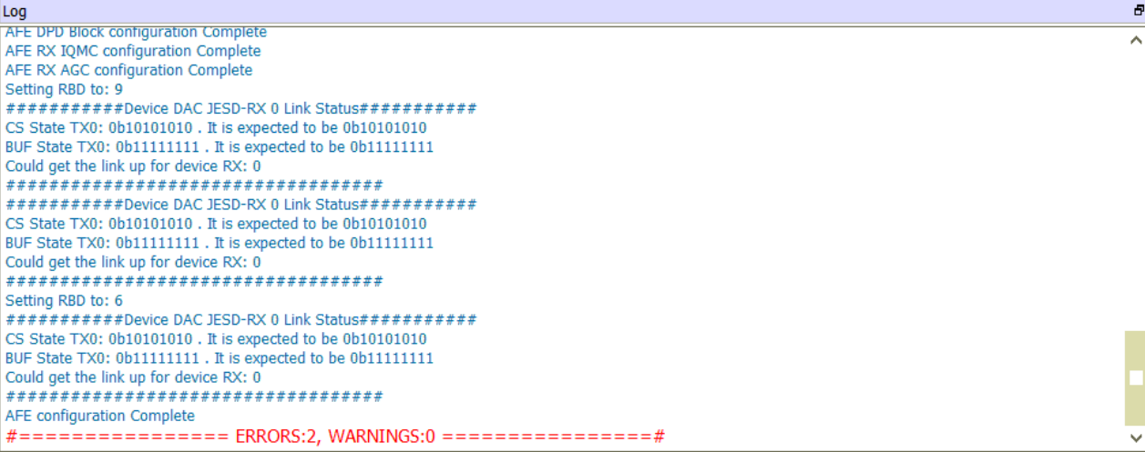 Figure 4-16 AFE Configuration Complete
Showing Link Up for the Device's JESD RX
 - After the
AFE7769D configuration is complete in the TI AFE77xxD Latte software press enter on
the Arm node (Teraterm) to recalibrate the FPGA XCVRs (Rx only) to complete the
JESD204C link up on FPGA. Figure 4-17 shows the link status report in the FPGA.
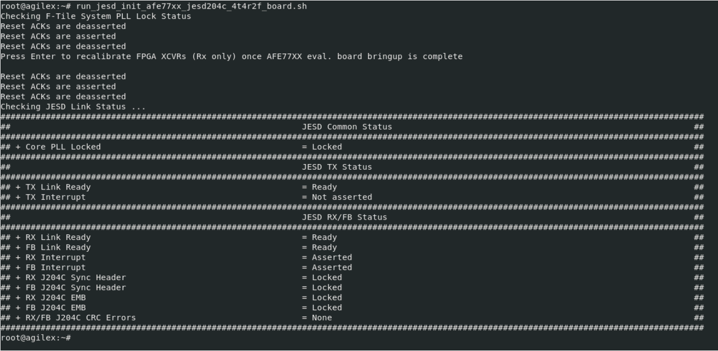 Figure 4-17 Completion of JESD204C
Linkup With Status Report for the Link
 - Run the ifconfig command to
see the IP address for the eth0 interface. Figure 4-18 shows an example block of code.

- If the eth0 interface does not appear like in the image above use the ifconfig eth0 192.168.0.1 up command to bring the interface up. Then use the ifconfig eth0 192.168.0.1 netmask 255.255.255.0 command to set the IP address of the interface
- Then, you can use the
ifconfig command to check that the interface has the IP
address assigned, see Figure 4-18 as reference.
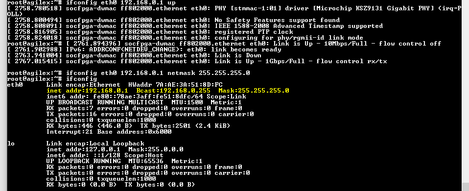 Figure 4-18 Confirmation
That the eth0 Interface has the Correct IP Address
- To be able to output signals from the
TX RF ports and input signals from the RX and FB RF ports, the "Channel TDD" needs
to be set for the required channels under test. This is done by going to the
"RXFB-Test" page in the AFE77xxD GUI by clicking on "RXFB-Test" on the left side of
the software window. In the "Channel TDD" box on this page, click on the red dots to
make them green, and finally click the "Set Tdd" button; see Figure 4-20.
 Figure 4-20 TDD Configuration for TX
to RX Test
Figure 4-20 TDD Configuration for TX
to RX TestNote that when testing the FB channels, the TDD for the RX channels should not be set (such that, the dots for the RX channels are not green), see Figure 4-21.
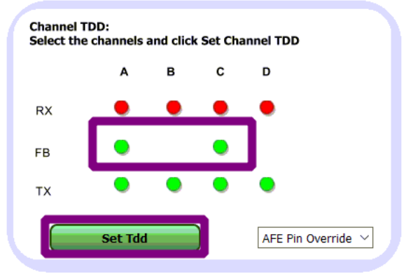 Figure 4-21 TDD Configuration for TX
to FB Test