SBAU428 September 2023 AFE7728D , AFE7768D , AFE7769 , AFE7769D , AFE7799 , AFE7920 , AFE7921 , AFE7952 , AFE7988 , AFE7989 , AFE8030 , AFE8092
2 Hardware Setup
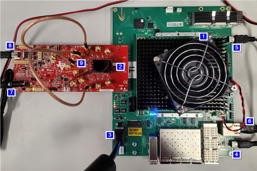
The following section provides a step-by-step walkthrough of the reference design setup from a hardware (HW) perspective, along with a visual representation of the setup at the end.
Steps:
- Mount the Agilex Embedded SOM7 (eSOM7) on the TI carrier board.
- Mount the AFE7769DEVM on the FMC+ slot of the TI carrier board.
- Plug the +12V 6-pin ATX PCIe power connector into the TI carrier.
- Connect a micro USB from the host PC to the USB connector J23 of the TI carrier for UART access to HPS (Arm® node).
- Connect a micro USB from the host PC to the USB connector J24 of the TI carrier for programming the Agilex FPGA image containing RF Interface framework over JTAG.
- Connect an Ethernet cable to the RJ45 port (J21) of the TI carrier for transferring files across the network.
- Connect a 5.5V, 5A power supply to the TI AFE7769DEVM.
- Connect a mini-USB cable between host PC (Windows) and mini-USB port on TI AFE7769D evaluation card for configuring the chips on the evaluation card using customized TI AFE77xxD Latte software (version 0.4.0) with the provided configuration file.
- SMA cables connected from TX RF ports
to RX/FB RF ports.
- Connections should be as
follows for TX to RX RF ports:
- TX1 (J7) to RX1 (J1)
- TX2 (J8) to RX2 (J2)
- TX3 (J9) to RX3 (J3)
- TX4 (J10) to RX4 (J4)
- Connections should be as
follows for TX to FB RF ports:
- TX1 (J7) to FB1 (J5)
- TX2 (J8) to FB2 (J6)
- Connections should be as
follows for TX to RX RF ports:
When powering on the HW setup, power on the Agilex eSOM7 TI Carrier before powering on the TI AFE7769DEVM. When powering off the HW setup, power off the TI AFE7769DEVM before powering off the Agilex eSOM7 TI Carrier. For the end result of the HW setup, see Figure 2-1.
Note: The Agilex eSOM7 can come with a Skyworks Si5518 timing
module (ASY-00-00048 Rev 2). This is not required for the purposes of this
guide.
 Figure 2-1 Hardware Setup, AFE7769DEVM and
Agilex eSOM7