SBAU479 December   2024 TAA3020


  1.   1
  2. 1Features
  3. 2Description
  4.   Trademarks
  5. 3Evaluation Module Overview
    1. 3.1 Introduction
    2. 3.2 Kit Contents
    3. 3.3 Specifications
    4. 3.4 Device Information
  6. 4Hardware Overview
    1. 4.1 AC-MB Settings
      1. 4.1.1 Audio Serial Interface Settings
        1. 4.1.1.1 USB
        2. 4.1.1.2 Optical or Auxilary Analog Audio Input
        3. 4.1.1.3 External
      2. 4.1.2 AC-MB Power Supply
    2. 4.2 TAA3020EVM-PDK Hardware Settings
      1. 4.2.1 Line Inputs
      2. 4.2.2 Onboard Microphone Configuration
      3. 4.2.3 External Microphone Configurations
  7. 5Software Overview
    1. 5.1 PurePath Console 3 Installation
    2. 5.2 TAA3020EVM GUI Installation
      1. 5.2.1 Software Setup
  8. 6GPIO1 Settings
  9. 7Master Mode Operation
  10. 8Quick Start
    1. 8.1 Configuring the Audio Serial Bus for the I2S Output
    2. 8.2 Saving a Configuration
  11. 9Schematic and Bill of Materials
    1. 9.1 TAA3020EVM-PDK Schematic and Bill of Materials
      1. 9.1.1 TAA3020EVM-PDK Schematic
      2. 9.1.2 TAA3020EVM-PDK Bill of Materials
    2. 9.2 AC-MB Schematic and Bill of Materials
      1. 9.2.1 AC-MB Schematic
      2. 9.2.2 AC-MB Bill of Materials
    3. 9.3 Matlab Audio Capture Example

Audio Serial Interface Settings

The AC-MB provides the digital audio digital signals to the evaluation module from the universal serial bus (USB), optical, stereo jack, and external audio serial interface (ASI) header. Figure 4-1 shows a block diagram of the ASI routing on the AC-MB.
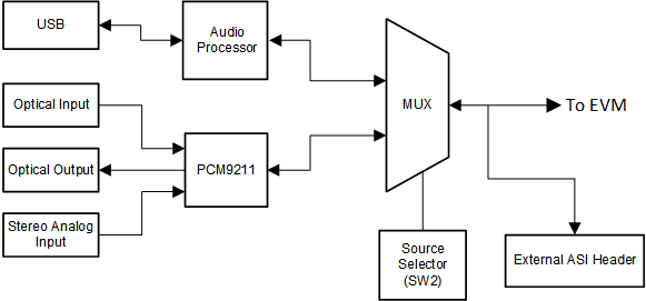
TAA3020 AC-MB Audio Serial Interface RoutingFigure 4-1 AC-MB Audio Serial Interface Routing

Switch SW2 on the AC-MB selects the audio serial bus that interfaces with the TAA3020EVB. Next to switch SW2, the AC-MB has a quick reference table to identify the audio serial interface source options and switch settings. The AC-MB acts as the master for the audio serial interface, with three different modes of operation: USB, optical or analog, or external ASI.