SBOA596 May 2024 ADS124S08 , INA326 , MSPM0G3507 , OPA387 , PGA900 , REF200
3.2 Current Excitation
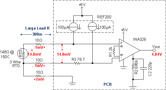
Another way to remove the common voltage for RTD and NTC application is to use two exactly the same current source to excite RTD and NTC and an auxiliary offset resistor. The value of auxiliary offset resistor can be equal the value of RTD and NTC resistor at start point temperature. TI: REF200 includes two exactly same constant current source and can meet this application. The typical application circuit is shown as Figure 3-2.
 Figure 3-2 RTD Signal Conditioning
Circuit Based Constant Current Source
Figure 3-2 RTD Signal Conditioning
Circuit Based Constant Current SourceIn Figure 3-2, R3 is auxiliary offset resistor for remove common voltage of RTD under approximately-54℃ since the application measure temperature in range of -50℃approximately150℃ with a 100Ω RTD sensor. In -54℃, the RTD resistor is 78.7Ω, then 100uA excitation current can produce the common voltage of 7.87mV. this common voltage can be removed by instrument amplifier INA326. The function between RTD resistor vary with output voltage as shown in Equation 2.
Equation 2 shows that the output voltage is linear with resistor varies. The gain can be adjusted according to specific application. The temperature can be deduced by the output voltage.