SBOK083A August 2024 – October 2024 TMUX582F-SEP
5.1 Single-Event Latch-Up (SEL) Results
During SEL characterization, the device was heated using forced hot air, maintaining device temperature at 125°C ± 5°C. A FLIR (FLIR ONE Pro LT) thermal camera was used to validate die temperature to make sure the device was being accurately heated (see Figure 3-7). The species used for SEL testing was a silver (109Ag) ion at an energy of 15MeV/µ with an angle-of-incidence of 0° for an LETEFF of 43MeV-cm2/ mg. A fluence of approximately 1 × 10⁷ ions / cm2 were used for the runs.
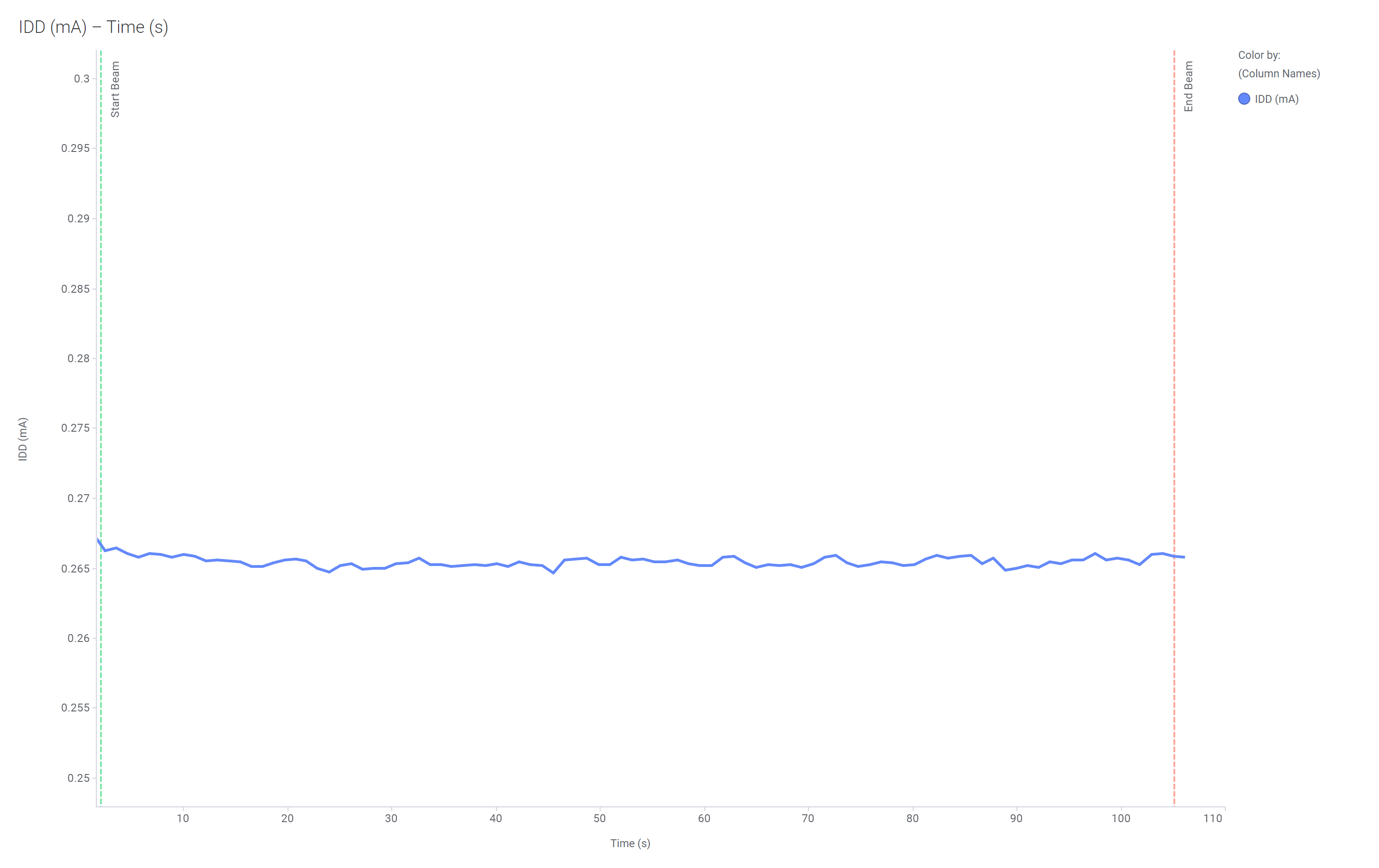
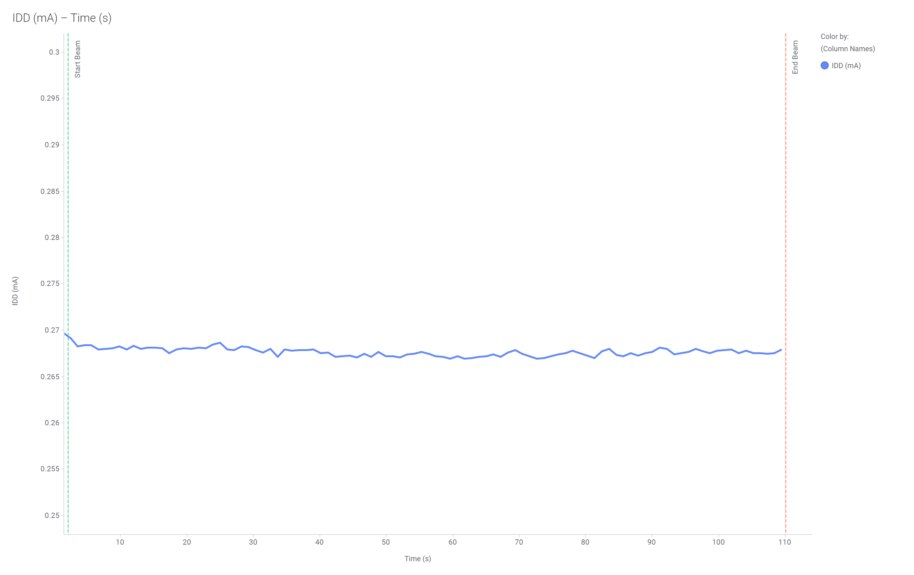
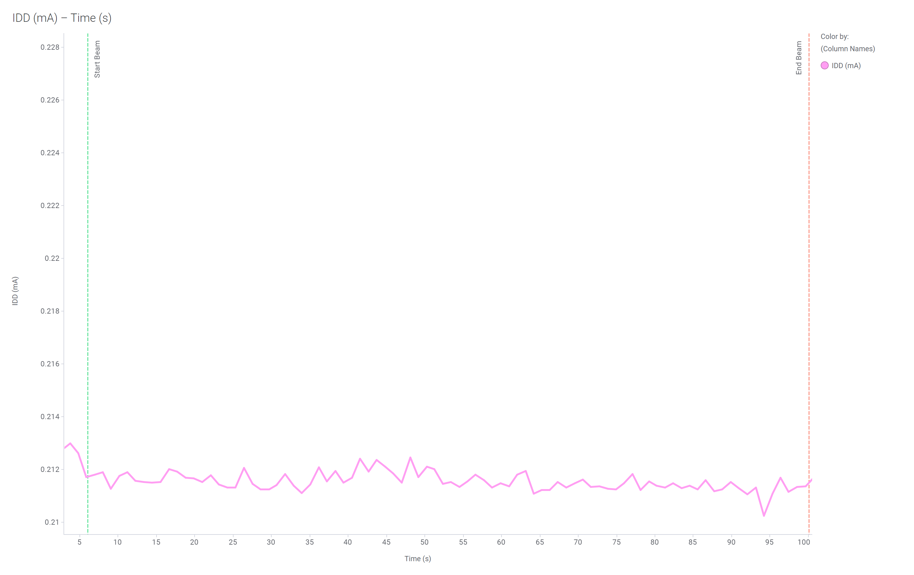
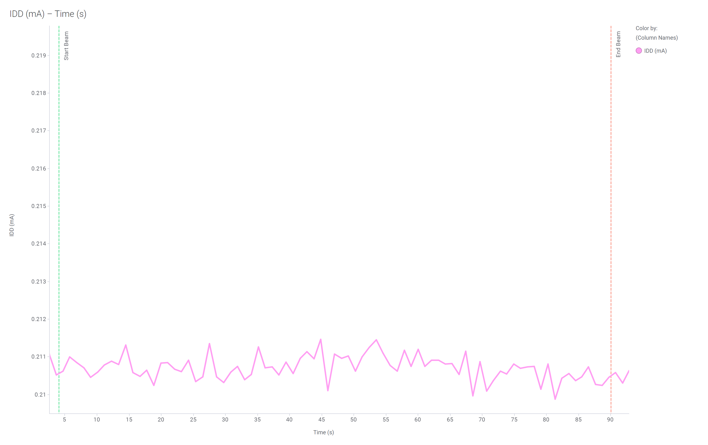
The three devices were powered up and exposed to the heavy-ions using the maximum recommended operating conditions under multiple bias schemes using two National Instruments PXI Chassis PXIe-4139 channels and a Keysight 33600A Waveform Generator for Bias #1, and three National Instruments PXI Chassis PXIe-4139 channels for Bias #2 and #3. The run duration to achieve this fluence was approximately one to two minutes. As listed in Table 5-6, no SEL events were observed during the 15 runs, indicating that the TMUX582F-SEP is SEL-free. Figure 5-1 and Figure 5-2 show the plot of current versus time for runs number 4, 9, 14 and 15, respectively.
| Run Number | Unit Number |
Bias |
Ion | Distance (mm) |
Angle | Temperature (°C) |
LETEFF (MeV.cm2/mg) |
FLUX (ions × cm2/mg) |
Fluence (# ions) |
SEL Event Occurred? |
|---|---|---|---|---|---|---|---|---|---|---|
|
1 |
1 |
1 |
Ag | 40 | 0° | 128 | 43 | 1.0E+05 | 1.0E+07 | No |
|
2 |
1 |
1 |
Ag | 40 | 0° | 128 | 43 | 1.0E+05 | 1.0E+07 | No |
|
3 |
1 |
1 |
Ag | 40 | 0° | 128 | 43 | 1.0E+05 | 1.0E+07 | No |
|
4 |
2 |
1 |
Ag | 40 | 0° | 122 | 43 | 1.0E+05 | 1.0E+07 | No |
|
5 |
2 |
1 |
Ag | 40 | 0° | 122 | 43 | 1.0E+05 | 1.0E+07 | No |
|
6 |
2 |
1 |
Ag | 40 | 0° | 122 | 43 | 1.0E+05 | 1.0E+07 | No |
|
7 |
3 |
1 |
Ag | 40 | 0° | 124 | 43 | 1.0E+05 | 1.0E+07 | No |
|
8 |
3 |
1 |
Ag | 40 | 0° | 124 | 43 | 1.0E+05 | 1.0E+07 | No |
|
9 |
3 |
1 |
Ag | 40 | 0° | 124 | 43 | 1.0E+05 | 1.0E+07 | No |
|
10 |
1 |
2 |
Ag |
40 |
0° |
125 |
43 |
1.0E+05 | 1.0E+07 |
No |
|
11 |
1 |
3 |
Ag |
40 |
0° |
125 |
43 |
1.0E+05 | 1.0E+07 |
No |
|
12 |
2 |
2 |
Ag |
40 |
0° |
123 |
43 |
1.0E+05 | 1.0E+07 |
No |
|
13 |
2 |
3 |
Ag |
40 |
0° |
123 |
43 |
1.0E+05 | 1.0E+07 |
No |
|
14 |
3 |
3 |
Ag |
40 |
0° |
126 |
43 |
1.0E+05 | 1.0E+07 |
No |
|
15 |
3 |
2 |
Ag |
40 |
0° |
126 |
43 |
1.0E+05 | 1.0E+07 |
No |
 Figure 5-1 Current Versus Time for Run #4
of the TMUX582F-SEP at T=125°C
 Figure 5-2 Current Versus Time for Run #9
of the TMUX582F-SEP at T=125°C
 Figure 5-3 Current Versus Time for Run
#14 of the TMUX582F-SEP at T=125°C
 Figure 5-4 Current Versus Time for Run
#15 of the TMUX582F-SEP at T=125°C