SBOU180B november   2016  – july 2023 INA260


  1.   1
  2.   INA260EVM-PDK and Software Tutorial
  3.   Trademarks
  4. 1Overview
    1. 1.1 INA260EVM-PDK Contents
    2. 1.2 INA260EVM-PDK Features
    3. 1.3 Related Documentation from Texas Instruments
  5. 2INA260EVM-PDK Hardware
    1. 2.1 SM-USB-DIG Platform Description
    2. 2.2 INA260EVM PCB Description
      1. 2.2.1 EVM Power Supply
      2. 2.2.2 EVM Analog Inputs
    3. 2.3 EVM Digital Inputs and Outputs
  6. 3INA260EVM-PDK (Rev A) Setup
    1. 3.1 One-Time GUI Software Installation
    2. 3.2 INA260EVM Jumper Settings
    3. 3.3 Connecting the Hardware
    4. 3.4 System Power-Up
  7. 4INA260EVM GUI Software
    1. 4.1 Configuration Tool
      1. 4.1.1 Step 1: Set the I2C Address
      2. 4.1.2 Step 2: Configure Operation
      3. 4.1.3 Step 3: Set Conversion Times
      4. 4.1.4 Step 4: Configure Alert
    2. 4.2 Results Bar
    3. 4.3 Graph Tool
    4. 4.4 Registers Tool
  8. 5INA260EVM Documentation
    1. 5.1 Schematic
    2. 5.2 PCB Layout
    3. 5.3 Bill of Materials
  9. 6Revision History

Step 1: Set the I2C Address

The first step to configuring the INA260 from the EVM GUI is setting up communication. As indicated by Table 2-2, the address bits A0 and A1 may represent up to 16 different INA260 devices communicating over a single I2C bus, where each device is identified by a unique target address. Therefore, step 1 involves selecting the correct A0 and A1 values that represent the target address of the INA260 installed on the EVM. In other words, the states of A0 and A1 in the GUI must match the jumper settings chosen for J2 and J3 on the EVM. The equivalent hexadecimal value of the target address is displayed in the box labeled I2C Address in Figure 4-2.
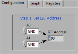
GUID-3FC08530-55CF-4783-81E2-53603807F625-low.gif Figure 4-2 Target Address Setting