SBOU246 January 2022 TMP61 , TMP61-Q1 , TMP63 , TMP63-Q1 , TMP64 , TMP64-Q1
1.3 NTC Versus Silicon-Based Linear Thermistor Trade-Offs
The configuration of the temperature sensing circuit in one's design will depend on any number of factors. While voltage-biased thermistors are simpler to construct, current-biased thermistors have a wider dynamic voltage range, greater stability, and higher accuracy across the temperature range for the output voltage VTEMP.
The typical NTC thermistor has a tolerance range from (1% to 5%) between temp extremes, although this can be higher for some NTC thermistors, while the TMP61 thermistor has a tolerance of (0.5% to 1.5%) between extremes [–40°C, +150°C] which can be seen in Figure 1-2 below.
 Figure 1-2 Resistance Tolerance of Typical NTC Thermistor vs. TMP6 Linear Thermistor.
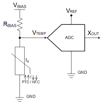
 The thermistor's greatest strength is its simplicity in design. With a voltage-biased or current-biased network, a voltage drop across the thermistor or a current can be passed through the thermistor to be measured for sensing. The main configurations for a thermistor circuit are voltage-biased, as demonstrated in the voltage divider configuration in Figure 1-3, or current-biased, as shown in Figure 1-4. The output voltage, VTEMP, can be fed to an ADC for digital processing of the temperature data in the MCU.
 Figure 1-3 Thermistor Voltage Divider Circuit.
  Figure 1-4 Thermistor Current Source Circuit.
 When looking at the characteristics of an NTC thermistor, it should be noted that when the ambient temperature is hot, the NTC thermistor presents a challenge to see what the temperature is at due to the low sensitivity at these higher temperatures. For easier software processing of incoming temperature data, one might need to linearize their NTC thermistor's R-T table. For NTC thermistors, this typically requires a fixed resistance value in parallel with the thermistor. Figure 1-5 shows a typical NTC thermistor voltage divider circuit with a parallel resistor of RP and a bias resistor RBIAS. A comparison of the voltage response of a typical NTC thermistor voltage divider, typical linear thermistor voltage divider and NTC thermistor voltage divider with parallel resistance is shown in Figure 1-6.
 Figure 1-6 NTC Thermistor With and Without a Linearization Resistor vs. TMP61 Thermistor Temperature Voltages.
 Thiscan work for a limited temperature range, but it is more difficult to linearize an NTC thermistor over the entire temperature range and cannot be done with hardware only. Conversely, linear thermistors are fabricated with a linear R-T characteristic curve, which eliminates the requirement for a fixed-value resistor in parallel with the thermistor.
System designers may require a calibration on thermistors to ensure accuracy across the operating range of the device. To achieve higher accuracy across this range, NTC thermistors require multiple-point calibration at different temperature values such as -40°C, 25°C, and 125°C due to the non-linearity of an NTC thermistor. The same theory can be applied to a linear thermistor, but because of the linearity, only a single-point calibration (at 25°C, for example) is needed. Therefore, using a linear thermistor will save on manufacturing time and reduce memory demands on the MCU for temperature processing. Refer to the Thermistor Design Tool for additional information on calibration with the TMP6 linear thermistor family of devices.