SBOU255 January 2021 INA183
3.1 Measurement With Shunt
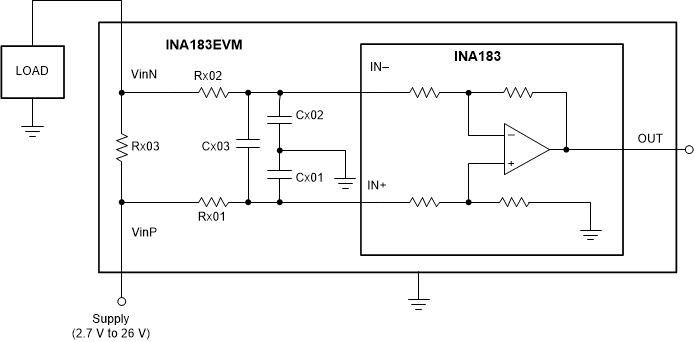
This connection method allows the user to install a shunt resistor on the EVM and connect the common-mode voltage and load to incorporate the test device directly into a sample application, as Figure 3-1 shows. To configure a measurement evaluation with a shunt, follow these procedures.
- Install a shunt resistor into the Rx03 (x=1, 2 or 3) location.
- Connect the common-mode voltage to the VinP terminal using either the surface mount or through hole test point. Solder test leads on to the test points when necessary for reliable connection.
- Connect load to the VinNterminal.
 Figure 3-1 Measurement With Shunt