SCLA071 August 2024 TPLD1201 , TPLD1201-Q1 , TPLD1202 , TPLD1202-Q1 , TPLD801 , TPLD801-Q1
3 How to Configure a Lookup Table
InterConnect Studio (ICS) is the software used to configure a TPLD. Once ICS is launched and a device is selected. Figure 3-1 shows the default configuration of a LUT when the LUT is added to a design. The name field can be set to any value using alpha numeric characters. This value then is always present just below the block in the design space. The label field is a multiline version of the name field. The value entered there is always present in the design space above the block. More information on these fields can be found in ICS User Guide. To change the amount of inputs available select the inputs drop down and select the desired number. A higher input hardware LUT can be allocated to a lower input count LUT in InterConnect Studio. For example when using a 2 input LUT in the design a 3 input LUT can be allocated. In this instance the extra input is tied to ground internally and the equation/table calculator automatically accounts for that input being 0 constantly.
 Figure 3-1 Default LUT config
The ways to configure the LUT are
- Using a predefined logic
function. Those options are
- AND
- OR
- XOR
- NAND
- NOR
- XNOR
- INVA
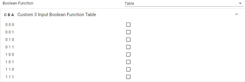
- Using a table as shown in Figure 3-3
- Writing an equation as shown in Figure 3-4. For more information on allowed characters please see ICS User Guide.
These options can be selected from the Boolean function field as shown in Figure 3-2
 Figure 3-2 LUT Selectable Options
 Figure 3-3 LUT Table Option
 Figure 3-4 LUT Equation Option